
Match the following : Codes :List - I List - II (circuit in the original question) (a) JFET VGS = 0V (i) 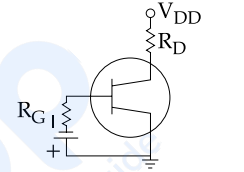
(b) JFET self-bias (ii) 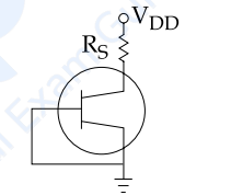
(c) JFET Fixed bias (iii) 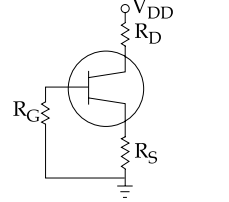
(d) FET Low Frequencies circuit (iv) 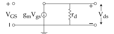
a-(ii), b-(iii), c-(i), d-(iv)
d → (iv) is immediate and anchors the answer. Only one of the four figures contains no supply rail and no bias resistors at all — it is a model, not a circuit. The dependent current source \(g_mV_{gs}\) in parallel with the drain resistance rd is the standard low-frequency small-signal equivalent of a FET. It is "low frequency" precisely because the interelectrode capacitances Cgs, Cgd and Cds have been omitted; adding them gives the high-frequency model.
c → (i), fixed bias. This is the only circuit with a separate gate battery. The gate resistor carries no DC current, so the whole battery voltage appears across the junction:
\(V_{GS}=-V_{GG}\)
Simple, but poor — it needs a second supply and gives no compensation for the wide spread in IDSS and VP between devices.
b → (iii), self-bias. The distinguishing feature is RS in the source lead with RG returning the gate to ground. Drain current through RS raises the source above ground while the gate stays at 0 V, so the junction is automatically reverse biased by the device's own current:
\(V_{GS}=-I_DR_S\)
The negative feedback is what makes it self-correcting: if ID tries to rise, VGS becomes more negative and pulls it back. No second supply is needed.
a → (ii), the VGS = 0 arrangement. The remaining figure has the gate tied directly back to the source, forcing \(V_{GS}=0\), so the device sits at
\(I_D=I_{DSS}\)
This is not really an amplifier bias at all — a JFET wired this way is a two-terminal constant-current source, and it is exactly how current-regulator diodes are made.
Assemble. a-(ii), b-(iii), c-(i), d-(iv) — option 4.
The one-glance discriminator.
| Look for | Scheme |
|---|---|
| A second battery at the gate | Fixed bias |
| RS present, gate to ground | Self-bias |
| Gate shorted to source | VGS = 0, ID = IDSS |
| No supply rail, a gmVgs source | Small-signal model |
Hence, the correct matching is a-(ii), b-(iii), c-(i), d-(iv).
Similar Questions
In an FET, following characteristics are given :
1. JFET is called as variable current resistor.
2. JFET is called Voltage variable resistor.
3. \(g_{d}=g_{d0}\left(1-\dfrac{V_{GS}}{V_{P}}\right)\), where gd0 is value of drain to source conductance for zero bias.
4. \(g_{d}=g_{d0}\left(1+\dfrac{V_{GS}}{V_{P}}\right)^{2}\)Which one of the following is true ?
For MOSFET, consider the following statements
A. In triode region, FET works as voltage variable resistor
B. For p-channel MOSFET, if VSG \(\gt\) |VTp|, then transistor will be in off mode
C. Amplification factor is inversly proportional to the value of VGS/Vp.
D. In saturation region, FET is used as amplifier.
E. For depletion MOSFET, channel is diffused and current flows even if VGS is zero
Choose the correct answer from the options given below :
Transfer characteristics for n-channel FET as a function of temperature T is shown in the figure
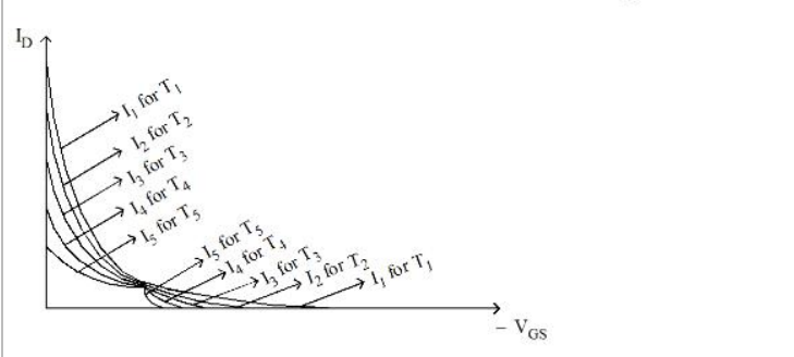
Choose the correct answer from the options given below :
When gate to source voltage of a FET changes from –5.2 volt to –5 volts, the corresponding drain current changes from 1 mA to 1.3 mA, the transconductance is
In a JFET the gate to source voltage is given as
In a JFET self-bias configuration shown below :
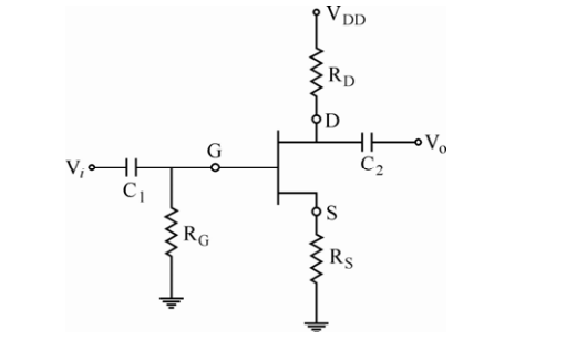
The drain current is
(a) \(K\dfrac{W}{L}(V_{gs}-V_{th})V_{ds}\)
(b) \(I_{DSS}\left(1-\dfrac{I_DR_S}{V_P}\right)^{2}\)
(c) \(I_{DSS}\left(1+\dfrac{I_DR_S}{V_P}\right)^{2}\)
(d) \(K\dfrac{W}{L}(V_{gs}-V_{th})^{2}\)
Out of these which are correct ?
Assertion (A) : FET is a device, which depends for its operation on the control of field or voltage due to applied current.
Reason (R) : FET has a very high input resistance of the order of mega-ohms. It is also immune to radiations.
Which of the following statements are valid for JFET ?
(a) \(I_{DS}=I_{DSS}\left(1-\dfrac{V_{GS}}{V_P}\right)\)
(b) \(I_{DS}=I_{DSS}\left(1+\dfrac{V_{GS}}{V_P}\right)\)
(c) \(\mu=\dfrac{g_m}{r_d}\)
(d) \(\mu=g_m\cdot r_d\)
Options :
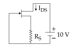
The JFET in a circuit shown in Figure, has an IDSS = 10 mA and Vp = − 5V. The value of resistance RS for a drain current IDS = 6.4 mA is (Choose the nearest value)
In a certain FET circuit, VGS = 0V, VDD = 15V, IDSS = 15 mA, and RD = 470Ω. If RD is decreased to 330 Ω, IDSS is :
Important Questions from Field Effect Transistors
Which of the following is the characteristic of Field-effect transistor?
- In junction field effect transistor, the drain current can be approximated as:
The expression for the transconductance (g m) of a JFET is:
Field Effect transistor is:
The main drawback of a JFET is its



