
In the circuit shown below, the output Y1 and Y2 for the given initial condition Y1 = Y2 = 1 and after four input pulses will be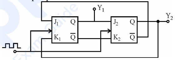
Y1 = 1, Y2 = 1
The decisive fact is not the detail of the wiring but the length of the state cycle.
Two flip-flops give four possible states — 00, 01, 10, 11 — and a synchronous machine with cross-coupled J-K inputs of this kind steps through all four before repeating. Its cycle length is therefore 4.
Four clock pulses advance the machine by exactly one complete cycle, so it returns to whatever state it started in:
| Pulse | Y1 Y2 |
|---|---|
| Start | 1 1 |
| After 1 | 0 1 |
| After 2 | 0 0 |
| After 3 | 1 0 |
| After 4 | 1 1 — back to the start |
So after four pulses Y1 = 1, Y2 = 1 — option 1.
The general principle, which saves all the tracing. For any counter of modulus N, the state after n pulses depends only on \(n\bmod N\). Here
\(4\bmod4=0\)
so the machine is back at its starting point regardless of what that starting point was. The same argument gives the answer for 8, 12 or 400 pulses, and it also shows that only pulse counts not divisible by 4 need any real work.
Why the answer is robust to the wiring detail. Whether the cross-coupling produces an ordinary binary up-counter (00 → 01 → 10 → 11) or a Johnson twisted-ring sequence (11 → 01 → 00 → 10), both are four-state cycles that use every state exactly once. Either reading returns to the initial condition after four clocks, which is why option 1 stands whichever way the figure is traced.
The word "synchronous" matters too: both flip-flops receive the same clock edge, so all state changes occur together and the next state depends only on the present state and the input equations. In a ripple counter the second stage would be clocked by the first, and although the count sequence would be the same, the outputs would be momentarily wrong during the propagation delay.
The answer is flagged for confirmation because the exact J and K connections in the printed figure are hard to trace with certainty.
Hence, after four pulses Y1 = 1, Y2 = 1.
Similar Questions
The truth table of D flip-flop is given below:
C D Qn+1 O X Qn (Last State) $\uparrow$ 0 0 $\uparrow$ 1 1 Choose exact characteristic equation based on above Truth Table
Assertion (A) : Delay flip flop is used to store a single bit either 0 or 1.
Reason (R) : It has only one input, when clock is high and D input is also high, the output resets.
Assertion (A) : Asynchronous sequential circuit is also called event driven circuit.
Reason (R) : Event driven circuit does not have clock to trigger change of state. The states are changed by the change in input signal of the previous stage.
Select your answer using the codes given below.
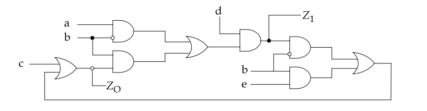
For the circuit shown below consider the two statements :
Assertion (A) : The circuit is sequential.
Reason (R) : There is a loop in circuit.
Select your answer using the codes given below.
Flip Flop can be used to make :
(a) Latches
(b) Bounce-elimination switches
(c) ADDER
(d) Encoder
Which of the statements given above are correct ?
Under which input condition, the J-K Flip-Flop toggles ?
Read the following statements :
(a) In a J-K Flip Flop, if J = K, the resulting Flip Flop is referred to as a T-type Flip Flop
(b) In a J-K Flip Flop, if J ≠ K, the resulting Flip Flop is referred to as a D-type Flip Flop
(c) An S-R Flip Flop cannot be converted into a T-type Flip Flop since S = R = 1 is not allowed.Which is correct ?
Which of the following statements are true regarding the operation of JK flip-flop ?
1. When K input is low and J input is high, the Q output of the flip flop is reset.
2. When K input is high and J input is low, the output Q of the flip flop is set.
3. When both the inputs K and J are low, the output Q does not change.
4. When both the inputs K and J are high it is possible to set or reset the flip-flop (ie) the output toggle on next positive clock edge.Which one of the following is true ?
Assertion (A) : D-flip-flops are used as buffer register.
Reason (R) : Flip-flops are free from "race-around" condition.
Select your answer using the codes given below :
Read the following statements :
i. Gate is a combinational logic.
ii. JK Flip-flop in toggle mode is not combinational logic.
iii. MSJK FF suffers from race-around.
iv. Counters are sequential circuits.Which is correct ?
Important Questions from Sequential Circuits
A basic memory storage element in a digital system is:
The basic sequential logic building block in which the output follows the data input as long as the ENABLE input is active, is
What can be the maximum clock frequency of a 10-bit ripple counter which will not cause a count to skip, considering 10 ns propagation delay for each of the edge-triggered flip flops?
The output of a sequential circuit depends on
The basic building block of a sequential logic circuit is



