
For the circuit shown below consider the two statements : Assertion (A) : The circuit is sequential. Reason (R) : There is a loop in circuit. Select your answer using the codes given below.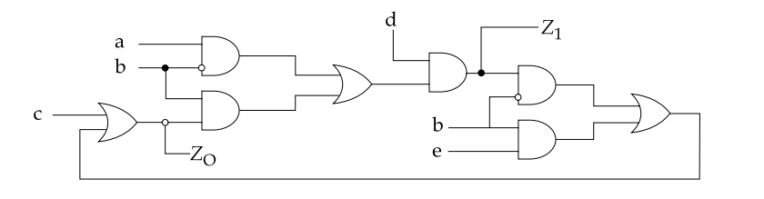
Both (A) and (R) are true and (R) is the correct explanation of (A)
Examine the reason first, since it is a matter of reading the diagram — true. The output of the right-hand OR gate is carried back along the bottom of the figure and re-enters the left-hand OR gate as one of its inputs. That is a genuine closed path: a signal can travel forward through the network and return to its own starting point.
Examine the assertion — true, and it follows from the loop. The two classes of logic circuit are distinguished by exactly this feature:
| Combinational | Sequential | |
|---|---|---|
| Structure | No feedback path | At least one feedback path |
| Output depends on | Present inputs only | Present inputs and past history |
| Memory | None | Present |
| Described by | A truth table | A state table or state diagram |
Because the fed-back signal re-enters the network, the present output helps determine the next output. The circuit therefore remembers, and a circuit with memory is sequential by definition.
Does the reason explain the assertion? Yes, completely. The loop is not merely present alongside the sequential behaviour — it is the cause of it. Break the feedback wire and the same gates become a purely combinational network whose outputs are a fixed function of a, b, c, d and e. So the code is 1.
Why feedback creates memory. Consider the simplest case, two cross-coupled NOR gates. Each output feeds the other's input, and the pair settles into one of two stable states and holds it after the inputs are removed — the SR latch, the basic memory cell from which all flip-flops are built. The same principle operates here.
What kind of sequential circuit this is. There is no clock input anywhere in the figure, so state changes happen as soon as an input changes and propagate at gate speed. That makes it an asynchronous (event-driven) sequential circuit rather than a clocked one — faster, but vulnerable to races and hazards if two inputs change together, which is why such designs require fundamental-mode operation and careful state assignment.
The rule to carry away. When asked to classify a logic diagram, trace every output backwards. If any path returns to a gate it has already passed through, the circuit is sequential; if every signal flows strictly left to right, it is combinational.
Hence, both statements are true and (R) is the correct explanation of (A).
Similar Questions
Read the following statements :
i. Gate is a combinational logic.
ii. JK Flip-flop in toggle mode is not combinational logic.
iii. MSJK FF suffers from race-around.
iv. Counters are sequential circuits.Which is correct ?
Which flip-flop can be used as latch ?
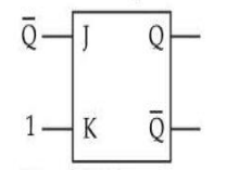
In a J-K FF, if J = Q and K = 1 (see figure). Assuming the flip flop was initially cleared and then clocked for 6 pulses, the sequence at the Q output will be :
Consider the following statements regarding registers and latches :
(A) Registers are made of edge triggered flip-flops whereas latches are made from level triggered flip flops
(B) Registers are temporary storage devices whereas latches are not
(C) A latch employs cross coupled feed back connections
(D) A register stores a binary word whereas a latch does notChoose the most appropriate answer from the options given below :
The toggle condition appears in J-K flip-flop when
A. J=1, K=1
B. J=0, K=0
C. J=0, K=1
D. J=1, K=0
E. J=0, K=1 and J=1, K=0
Choose the correct answer from the options given below :
Match List I with List II
LIST I (Diagram) LIST II (Sequential Circuit) A. 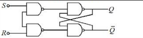
I. Edge triggered S-R flip flop B. 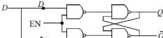
II. D Flip flop to SR flip flop C. 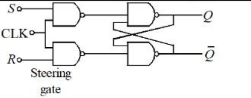
III. Gated Latch clocked flip flop D. 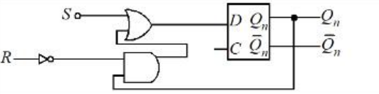
IV. Gated D Latch Choose the correct answer from the options given below:
The truth table of D flip-flop is given below:
C D Qn+1 O X Qn (Last State) $\uparrow$ 0 0 $\uparrow$ 1 1 Choose exact characteristic equation based on above Truth Table
Assertion (A) : Delay flip flop is used to store a single bit either 0 or 1.
Reason (R) : It has only one input, when clock is high and D input is also high, the output resets.
Assertion (A) : Asynchronous sequential circuit is also called event driven circuit.
Reason (R) : Event driven circuit does not have clock to trigger change of state. The states are changed by the change in input signal of the previous stage.
Select your answer using the codes given below.
Flip Flop can be used to make :
(a) Latches
(b) Bounce-elimination switches
(c) ADDER
(d) Encoder
Which of the statements given above are correct ?
Important Questions from Sequential Circuits
The basic sequential logic building block in which the output follows the data input as long as the ENABLE input is active, is
What can be the maximum clock frequency of a 10-bit ripple counter which will not cause a count to skip, considering 10 ns propagation delay for each of the edge-triggered flip flops?
The output of a sequential circuit depends on
The basic building block of a sequential logic circuit is
A 4bit synchronous counter uses flip-flops with a propagation delay time of 25ns each. The maximum possible time required for change of state will be



