For the different values of 'L' while keeping 'RL' as constant, following graph is obtained from the given circuit. Choose the correct ascending order from the options given below for the different values of ' L ' : 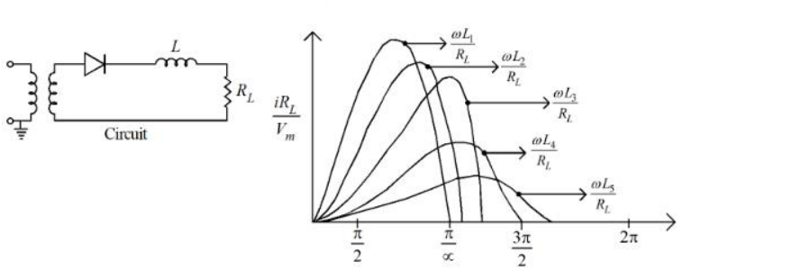
\(L_1 \lt L_2 \lt L_3 \lt L_4 \lt L_5\)
The circuit and the graph. A rectifier feeds a series inductor L and a load resistor RL. The figure plots the normalised load current \(i_{R_L}/V_m\) against angle, one curve per inductance value, each labelled by the dimensionless ratio
\(\dfrac{\omega L}{R_L} = \tan\phi\)
What the inductor does. An inductor opposes any change of current, \(v_L = L\,di/dt\), so it stores energy while the source voltage is high and releases it when the source falls. Two visible consequences follow as L increases with RL held constant:
1. The current waveform becomes smoother and flatter — the ripple shrinks, because a larger L resists the swing more strongly. In the limit of very large L the current becomes almost pure d.c.
2. The conduction extends past the point where the source voltage crosses zero; the stored energy keeps the current flowing (through the freewheeling path), so the conduction angle grows.
Reading the family of curves. Since \(\omega L/R_L\) rises in direct proportion to L, the curve labelled with the smallest ratio corresponds to the smallest inductance, and the labels run in order from the peakiest, most ripply waveform (L1) to the flattest, most extended one (L5). Therefore
\(L_1 \lt L_2 \lt L_3 \lt L_4 \lt L_5\)
Why the other options are impossible. Options 3 and 4 make all five inductances equal (0 or 1 nH), which could not produce five distinct curves at all — and with L = 0 there would be no smoothing whatsoever. Option 1 simply reverses the physics, implying the flattest curve belongs to the smallest inductance.
Practical significance. This is exactly why a rectifier output uses an L-C (choke-input) filter: raising L reduces the ripple factor and, once \(\omega L \gg R_L\), keeps the current continuous through the whole cycle, which improves the transformer utilisation and reduces the peak diode current.
Hence, the ascending order of inductance is \(L_1 \lt L_2 \lt L_3 \lt L_4 \lt L_5\).
Similar Questions
Consider the following rectifier circuits :
1. Half-wave rectifier without filter
2. Full-wave rectifier without filter
3. Full-wave rectifier with series inductance filter
4. Full-wave rectifier with capacitance filterThe sequence of these rectifier circuits in decreasing order of the ripple factor is
Assertion (A) : Capacitor input filter gives a high output voltage which drops as the load is increased.
Reason (R) : Capacitor input filters produce more heating in the rectifiers.
The ratio of peak to peak input ripple voltage to peak to peak ripple output voltage is known as:
Read the statements:
A. The O/P frequency of a half wave rectifier is equal to the input frequency
B. The O/P frequency of a full wave rectifier is double to the input frequency
C. The regulation of an excellent rectifier should be zero.
D. ripple factor in the full wave rectifier is 1.2.
Choose the correct statements from the options given below:
Statements regarding rectifier are :
A. RMS value of current in a half wave rectifier is \(\frac{I_m}{\sqrt{2}}\)
B. PIV of diode in a full wave bridge rectifier is Vm volts.
C. TUF and rectification efficiency for a rectifier are same parametrs.
D. Rectifier converts A.C. to rippled DC not pure D.C.
Choose the correct answer from the options given below:
In a rectifier the ripple factor can be expressed as
(a) \(\dfrac{I_{rms}}{I_{dc}}\) (b) \(\sqrt\dfrac{I_{dc}}{I_{rms}}\) (c) \(\sqrt{\left(\dfrac{I_{rms}}{I_{dc}}\right)^{2}-1}\) (d) \(\sqrt{1-\left(\dfrac{I_{rms}}{I_{dc}}\right)^{2}}\)
Which one of the above is correct ?
For a full-wave rectifier, which of the following statements are correct ?
(a) \(V_{dc}=\dfrac{2V_P}{\pi}\)
(b) \(f_{out}=2f_{in}\)
(c) \(V_{dc}=\dfrac{2\pi}{V_P}\)
(d) \(I_{dc}=\dfrac{I_m}{\sqrt{\pi}}\)
Options :
As compared to a full-wave rectifier using two diodes, the four diode bridge rectifier has the dominant advantage of :
In rectifiers :
(a) The efficiency of rectification is given by \(\eta=\dfrac{P_{ac}}{P_{dc}}\)
(b) The AC component on the output side : \(V_{ac}=\sqrt{V_{rms}^{2}-V_{dc}^{2}}\)
(c) Form factor is given by : \(FF=\dfrac{V_{dc}}{V_{rms}}\)
(d) Ripple factor is given by : \(RF=\sqrt{\left(\dfrac{V_{rms}}{V_{dc}}\right)^{2}-1}\)
Of these statements :
A half wave rectifier operates from 50 Hz supply and provides a peak output voltage of 60 V across the 600 Ω resistance. The value of capacitance for the capacitor filter would limit the peak to peak ripple voltage across load is 15 V :
Important Questions from Rectifier Circuits
PIV of a non conducting diode in a bridge rectifier is
The no-load output voltage of an ideal half wave rectifier is _______.
What is the minimum PIV required for a diode used in a full-wave rectifier circuit using a center-tapped transformer with a secondary voltage of 50V-0-50 V (rms)?
One of the following is a negative resistance device
Which of the following is NOT true for a rectifier?