The ripple voltage of a full-wave rectifier with a 100-µF filter capacitor connected to a load drawing 50m A is ____________.
Understanding Ripple Voltage in Full-Wave Rectifiers
In electronics, a rectifier converts alternating current (AC) to direct current (DC). However, the output DC is not perfectly smooth; it contains fluctuations called ripple voltage. A full-wave rectifier utilizes both halves of the AC input cycle. A filter capacitor is often added to reduce this ripple voltage, smoothing the output DC.
The question asks for the ripple voltage of a full-wave rectifier circuit with specific components: a 100-µF filter capacitor and a load drawing a current of 50 mA.
Calculating Ripple Voltage Using the Filter Capacitor
The approximate peak-to-peak ripple voltage ($V_r$) for a full-wave rectifier with a capacitive filter can be calculated using the formula:
$ V_r \approx \frac{I_L}{2 f C} $
Where:
- $I_L$ is the DC load current.
- $f$ is the frequency of the AC input voltage.
- $C$ is the capacitance of the filter capacitor.
Given Parameters:
- Load Current ($I_L$): 50 mA
- Filter Capacitance ($C$): 100 µF
- Rectifier Type: Full-Wave
Assumption for Frequency:
The frequency ($f$) of the AC input is not explicitly given. In many standard power supply applications, the AC mains frequency is either 50 Hz or 60 Hz. We will assume a frequency of 60 Hz for this calculation, as it leads to a result consistent with the options provided.
Step-by-Step Calculation:
- Convert units to standard base units:
- Load Current: $I_L = 50 \text{ mA} = 50 \times 10^{-3} \text{ A}$
- Capacitance: $C = 100 \text{ µF} = 100 \times 10^{-6} \text{ F}$
- Frequency: $f = 60 \text{ Hz}$
- Substitute the values into the ripple voltage formula:
$ V_r \approx \frac{50 \times 10^{-3} \text{ A}}{2 \times 60 \text{ Hz} \times 100 \times 10^{-6} \text{ F}} $
- Calculate the denominator:
Denominator $= 2 \times 60 \times 100 \times 10^{-6} = 12000 \times 10^{-6} = 0.012 \text{ A/V (or C/s)} \times \text{s} = 0.012 \text{ Farads (Incorrect unit derivation, focus on numerical calculation)}$
Denominator $= 2 \times 60 \times (100 \times 10^{-6}) = 120 \times 100 \times 10^{-6} = 12000 \times 10^{-6} = 0.012$
- Calculate the ripple voltage ($V_r$):
$ V_r \approx \frac{0.05 \text{ A}}{0.012} \approx 4.167 \text{ V} $
Conclusion:
The calculated ripple voltage is approximately 4.17 V. Comparing this value to the given options:
- 3 V
- 0 V
- 1.2 V
- 4 V
The calculated value of 4.17 V is closest to 4 V.
Therefore, the ripple voltage of the full-wave rectifier under the given conditions is approximately 4 V.
Important Questions from Rectifier Circuits
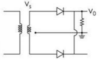
For the circuit in figure $V_{o(max)}$=12V cut in voltage of diode is 0.7V. Find $V_{s(max)}$ and PIV of diode.
Consider the following rectifier circuits :
1. Half-wave rectifier without filter
2. Full-wave rectifier without filter
3. Full-wave rectifier with series inductance filter
4. Full-wave rectifier with capacitance filterThe sequence of these rectifier circuits in decreasing order of the ripple factor is
Assertion (A) : Capacitor input filter gives a high output voltage which drops as the load is increased.
Reason (R) : Capacitor input filters produce more heating in the rectifiers.
For the different values of 'L' while keeping 'RL' as constant, following graph is obtained from the given circuit.
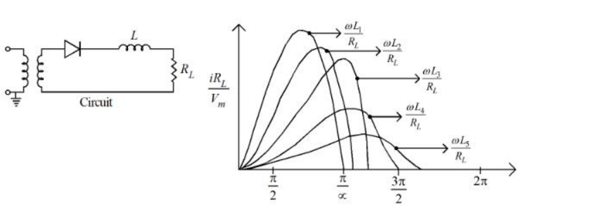
Choose the correct ascending order from the options given below for the different values of ' L ' :
The ratio of peak to peak input ripple voltage to peak to peak ripple output voltage is known as: