Consider the following rectifier circuits : 1. Half-wave rectifier without filter The sequence of these rectifier circuits in decreasing order of the ripple factor is
2. Full-wave rectifier without filter
3. Full-wave rectifier with series inductance filter
4. Full-wave rectifier with capacitance filter
1, 2, 3, 4
The list as printed is already in decreasing order of ripple — 1, 2, 3, 4, option 1 — because each entry improves on the one before it.
| Circuit | Ripple factor |
|---|---|
| 1. Half wave, no filter | 1.21 |
| 2. Full wave, no filter | 0.482 |
| 3. Full wave, inductor filter | \(\dfrac{R_{L}}{3\sqrt{2}\,\omega L}\) — a few per cent |
| 4. Full wave, capacitor filter | \(\dfrac{1}{4\sqrt{3}\,fCR_{L}}\) — well under one per cent |
Steps 1 to 2 — unfiltered rectifiers. Ripple factor is the ratio of the RMS ripple to the DC value,
\(\gamma=\dfrac{V_{r,rms}}{V_{DC}}=\sqrt{\left(\dfrac{V_{rms}}{V_{DC}}\right)^{2}-1}\)
For half-wave, \(V_{rms}=V_{m}/2\) and \(V_{DC}=V_{m}/\pi\), giving 1.21 — the ripple is larger than the DC it accompanies. Full-wave rectification fills in the missing half cycles, doubling the DC and halving the gap, and the figure falls to 0.482.
Steps 3 and 4 — adding a filter. An inductor in series opposes changes of current, and its reactance \(\omega L\) rises with the harmonic order, so it passes DC and blocks ripple. A capacitor across the load does the complementary job: it stores charge at each peak and supplies the load between peaks, holding the output near the peak value instead of letting it follow the sine down to zero.
Why the capacitor filter beats the inductor filter — the one comparison that decides between options 1 and a reordering. For the moderate load currents these questions assume, a practical capacitor of a few hundred microfarads gives ripple well below one per cent, while an inductor large enough to match would be bulky and expensive; the L-filter's ripple, being proportional to \(R_{L}\), is small only for heavy loads. The answer is flagged because the ordering of 3 against 4 depends on the component values assumed, and the question states none.
The two filters have opposite load behaviour, which is why an LC or π-section combines them: the capacitor suits light loads, the inductor heavy ones, and together they hold the ripple low across the range.
Hence, the decreasing order is 1, 2, 3, 4.
Similar Questions
Assertion (A) : Capacitor input filter gives a high output voltage which drops as the load is increased.
Reason (R) : Capacitor input filters produce more heating in the rectifiers.
For the different values of 'L' while keeping 'RL' as constant, following graph is obtained from the given circuit.
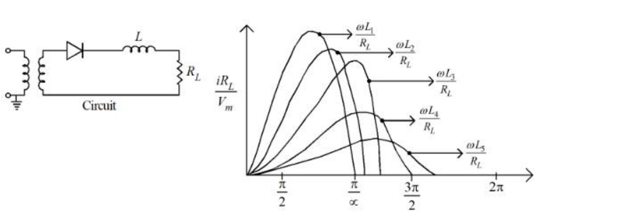
Choose the correct ascending order from the options given below for the different values of ' L ' :
The ratio of peak to peak input ripple voltage to peak to peak ripple output voltage is known as:
Read the statements:
A. The O/P frequency of a half wave rectifier is equal to the input frequency
B. The O/P frequency of a full wave rectifier is double to the input frequency
C. The regulation of an excellent rectifier should be zero.
D. ripple factor in the full wave rectifier is 1.2.
Choose the correct statements from the options given below:
Statements regarding rectifier are :
A. RMS value of current in a half wave rectifier is \(\frac{I_m}{\sqrt{2}}\)
B. PIV of diode in a full wave bridge rectifier is Vm volts.
C. TUF and rectification efficiency for a rectifier are same parametrs.
D. Rectifier converts A.C. to rippled DC not pure D.C.
Choose the correct answer from the options given below:
In a rectifier the ripple factor can be expressed as
(a) \(\dfrac{I_{rms}}{I_{dc}}\) (b) \(\sqrt\dfrac{I_{dc}}{I_{rms}}\) (c) \(\sqrt{\left(\dfrac{I_{rms}}{I_{dc}}\right)^{2}-1}\) (d) \(\sqrt{1-\left(\dfrac{I_{rms}}{I_{dc}}\right)^{2}}\)
Which one of the above is correct ?
For a full-wave rectifier, which of the following statements are correct ?
(a) \(V_{dc}=\dfrac{2V_P}{\pi}\)
(b) \(f_{out}=2f_{in}\)
(c) \(V_{dc}=\dfrac{2\pi}{V_P}\)
(d) \(I_{dc}=\dfrac{I_m}{\sqrt{\pi}}\)
Options :
As compared to a full-wave rectifier using two diodes, the four diode bridge rectifier has the dominant advantage of :
In rectifiers :
(a) The efficiency of rectification is given by \(\eta=\dfrac{P_{ac}}{P_{dc}}\)
(b) The AC component on the output side : \(V_{ac}=\sqrt{V_{rms}^{2}-V_{dc}^{2}}\)
(c) Form factor is given by : \(FF=\dfrac{V_{dc}}{V_{rms}}\)
(d) Ripple factor is given by : \(RF=\sqrt{\left(\dfrac{V_{rms}}{V_{dc}}\right)^{2}-1}\)
Of these statements :
A half wave rectifier operates from 50 Hz supply and provides a peak output voltage of 60 V across the 600 Ω resistance. The value of capacitance for the capacitor filter would limit the peak to peak ripple voltage across load is 15 V :
Important Questions from Rectifier Circuits
PIV of a non conducting diode in a bridge rectifier is
The no-load output voltage of an ideal half wave rectifier is _______.
What is the minimum PIV required for a diode used in a full-wave rectifier circuit using a center-tapped transformer with a secondary voltage of 50V-0-50 V (rms)?
One of the following is a negative resistance device
Which of the following is NOT true for a rectifier?