For the circuit in figure $V_{o(max)}$=12V cut in voltage of diode is 0.7V. Find $V_{s(max)}$ and PIV of diode. 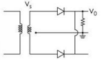
To solve this problem, let's analyze the given circuit and determine the maximum supply voltage \(V_{s(max)}\) and the Peak Inverse Voltage (PIV) of the diode.
First, identify the conditions under which the maximum output voltage \(V_o(max)\) is achieved. According to the problem, \(V_{o(max)} = 12 \text{ V}\).
Taking into account the diode's cut-in voltage of \(0.7 \text{ V}\), the maximum supply voltage can be calculated as:
- \(V_{s(max)} = V_{o(max)} + V_d = 12 \text{ V} + 0.7 \text{ V} = 12.7 \text{ V}\)
The PIV of the diode is the maximum reverse voltage the diode can withstand without breaking down. This is essentially twice the maximum output voltage in this type of rectifier circuit. Therefore, the PIV is:
- \(PIV = 2 \times V_{o(max)} = 2 \times 12 \text{ V} = 24.7 \text{ V}\)
Therefore, the correct answer is:
- \(V_{s(max)} = 12.7 \text{ V}\)
- PIV of the diode = 24.7 V
So, the correct answer is 12.7V, 24.7V, which corresponds to the given answer choice.
Note: In rectifier circuits, always consider the diode's cut-in voltage and understand that the PIV is a key factor in determining diode specifications to avoid breakdown during operation.
Important Questions from Rectifier Circuits
The ripple voltage of a full-wave rectifier with a 100-µF filter capacitor connected to a load drawing 50m A is ____________.
Consider the following rectifier circuits :
1. Half-wave rectifier without filter
2. Full-wave rectifier without filter
3. Full-wave rectifier with series inductance filter
4. Full-wave rectifier with capacitance filterThe sequence of these rectifier circuits in decreasing order of the ripple factor is
Assertion (A) : Capacitor input filter gives a high output voltage which drops as the load is increased.
Reason (R) : Capacitor input filters produce more heating in the rectifiers.
For the different values of 'L' while keeping 'RL' as constant, following graph is obtained from the given circuit.
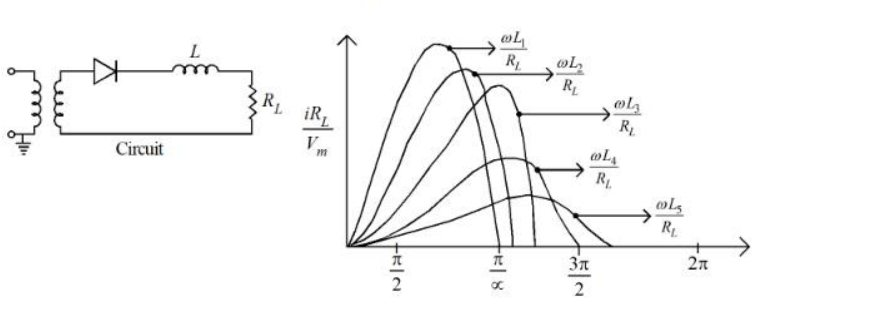
Choose the correct ascending order from the options given below for the different values of ' L ' :
The ratio of peak to peak input ripple voltage to peak to peak ripple output voltage is known as: