
The [Y] parameters of the network shown below are given as :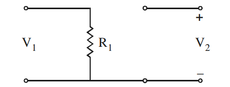
\(\begin{bmatrix}\dfrac{1}{R_1} & 0\\[4pt] 0 & 0\end{bmatrix}\)
What the Y parameters mean. They are the short-circuit admittance parameters, defined by
\(I_1=Y_{11}V_1+Y_{12}V_2, \qquad I_2=Y_{21}V_1+Y_{22}V_2\)
Each one is measured with the other port shorted, which is what makes them quick to read off a picture.
Read the topology. R1 hangs directly across port 1. The bottom rail is common to both ports, but the top terminal of port 2 is isolated — nothing joins it to the R1 node. So no current can ever enter or leave the upper terminal of port 2.
Step 1 — the two parameters with V2 shorted. Set V2 = 0 and apply V1. The whole of V1 sits across R1:
\(Y_{11}=\left.\dfrac{I_1}{V_1}\right|_{V_2=0}=\dfrac{1}{R_1}\)
Because port 2's upper terminal is open, that current cannot reach it:
\(Y_{21}=\left.\dfrac{I_2}{V_1}\right|_{V_2=0}=0\)
Step 2 — the two parameters with V1 shorted. Now drive port 2. Since its top terminal connects to nothing, no current flows anywhere:
\(Y_{22}=\left.\dfrac{I_2}{V_2}\right|_{V_1=0}=0, \qquad Y_{12}=\left.\dfrac{I_1}{V_2}\right|_{V_1=0}=0\)
Step 3 — assemble the matrix.
\([Y]=\begin{bmatrix}1/R_1 & 0\\ 0 & 0\end{bmatrix}\)
Where the distractors come from. Option 1 is the answer you would get if R1 were a shunt element common to both ports, i.e. if the two upper terminals were joined — then every entry becomes 1/R1 and the matrix is singular. Option 4 is the Y matrix of two independent resistors, one across each port. Option 2 is not even symmetric, so it cannot describe a reciprocal network built only from resistors — a useful one-second check, since reciprocity demands Y12 = Y21.
A note on existence. This network has a perfectly good Y matrix even though its Z matrix does not exist — with port 2 open the impedance parameters run to infinity. That asymmetry is the practical reason both descriptions are kept in circuit theory.
Hence, \([Y]=\begin{bmatrix}1/R_1 & 0\\ 0 & 0\end{bmatrix}\).
Similar Questions
Read the following statements :
ST 1 : y-parameters can be obtained from Z parameters.
ST 2 : It is not necessary to define y-parameters separately.Match the given lists :
List – I List – II a. Condition of reciprocity i. \(\dfrac{Z_{12}}{Z_{22}}\) b. h12 ii. Z12 = Z21 c. 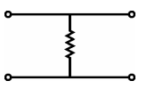 \(\begin{bmatrix}R&R\\R&R\end{bmatrix}\)
iii. Z d. Condition of symmetry iv. Z11 = Z22 Codes :
The T-parameters for the following cascaded network is :
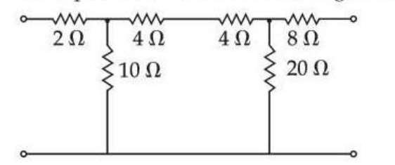
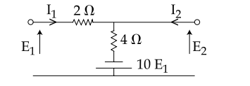
For the two-port network shown in figure, the z-parameter matrix is given by
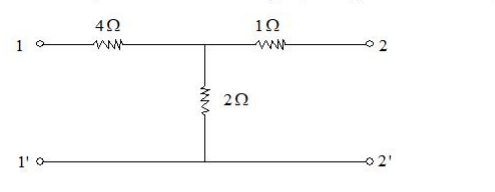
The z parameters z11 and z21 for the 2-port network shown in the given figure respectively are :
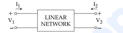
The two port network mentioned below can be characterized by four variables V1, V2, I1 and I2, in which only two can be independent.
The h-parameters of the two port network possesses the following :
(a) Linear network should contain no independent sources.
(b) V1 and V2 are taken as independent variables.
(c) V1 and I2 are taken as independent variables.
(d) I1 and V2 are taken as independent variables.Options :
Assertion (A) : In a two port network, with 4 terminals four types of parameters like impedance, admittance, hybrid and transmission are considered and they are related to each other.
Reason (R) : The assumption made for the above statement is that there are no independent sources and non-zero initial conditions within the linear port network.
Select your answer using the codes given below :
Important Questions from Two Port Networks
A two-port network has scattering parameters given \(\left[ s \right] = \left[ {\begin{array}{*{20}{c}} {{s_{11}}}&{{s_{12}}}\\ {{s_{211}}}&{{s_{22}}} \end{array}} \right]\). If the port 2 of the two-port is short-circuited, the s11 parameter for the resultant one-port network is
With 10 V dc connected at port A, the current drawn by 7 Ω connected at port B is
With 6 V dc connected at port A, 1 Ω connected at port B draws 7/3 A. If 8 V dc is connected to port A, the open circuit voltage at port B is
In a linear two – port network, when 10 V is applied to Port 1, a current of 4 A flows through Port 2 when it is short-circuited. When 5 V is applied to Port, a current of 1.25 A flows through a 1 Ω resistance connected across Port 2. When 3 V is applied to Port 1, then current (in Ampere) through a 2 Ω resistance connected across Port 2 is __________.
A network is said to be reciprocal if



