
With 10 V dc connected at port A in the linear nonreciprocal two-port network shown below, the following were observed: i) 1 Ω connected at port B draws a current of 3 A ii) 2.5 Ω connected at port B draws a current of 2 A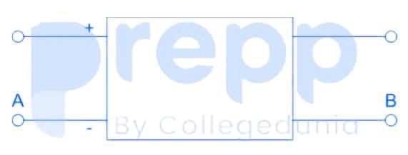
With 10 V dc connected at port A, the current drawn by 7 Ω connected at port B is
1 A
When 10 V is connected at port A the network is
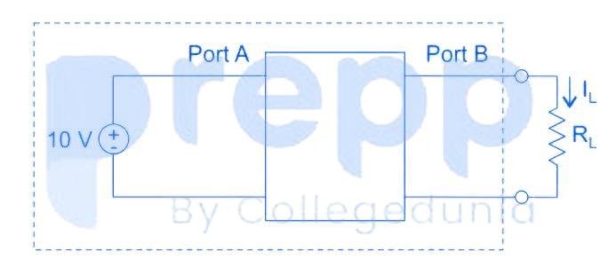
Now, we obtain Thevenin equivalent for the circuit seen at load terminal, let thevenin voltage is Vth ,10 V with 10 V applied at port A and thevenin resistance is Rth.
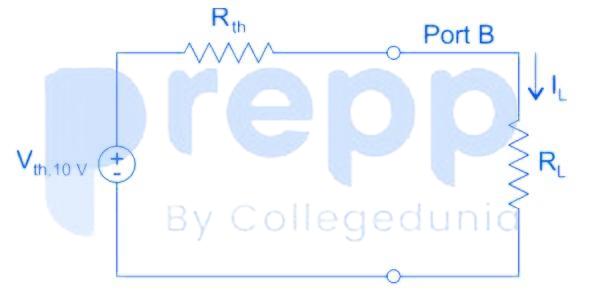
\(% MathType!Translator!2!1!LaTeX.tdl!LaTeX 2.09 and later! % MathType!MTEF!2!1!+- % feaagKart1ev2aqatCvAUfeBSjuyZL2yd9gzLbvyNv2CaerbuLwBLn % hiov2DGi1BTfMBaeXatLxBI9gBaerbd9wDYLwzYbItLDharqqtubsr % 4rNCHbGeaGqiVu0Je9sqqrpepC0xbbL8F4rqqrFfpeea0xe9Lq-Jc9 % vqaqpepm0xbba9pwe9Q8fs0-yqaqpepae9pg0FirpepeKkFr0xfr-x % fr-xb9adbaqaaeGaciGaaiaabeqaamaabaabaaGcbaaeaaaaaaaaa8 % qacaWGjbWdamaaBaaaleaapeGaamitaaWdaeqaaOWdbiabg2da9maa % laaapaqaa8qacaWGwbWdamaaBaaaleaapeGaamiDaiaadIgacaGGSa % GaaGymaiaaicdacaWGwbaapaqabaaakeaapeGaamOua8aadaWgaaWc % baWdbiaadshacaWGObaapaqabaGcpeGaey4kaSIaamOua8aadaWgaa % WcbaWdbiaadYeaa8aabeaaaaaaaa!45A9! {I_L} = \frac{{{V_{th,10V}}}}{{{R_{th}} + {R_L}}}% MathType!End!2!1! \)
For RL = 1 Ω, IL = 3 A
\(% MathType!Translator!2!1!LaTeX.tdl!LaTeX 2.09 and later! % MathType!MTEF!2!1!+- % feaagKart1ev2aqatCvAUfeBSjuyZL2yd9gzLbvyNv2CaerbuLwBLn % hiov2DGi1BTfMBaeXatLxBI9gBaerbd9wDYLwzYbItLDharqqtubsr % 4rNCHbGeaGqiVu0Je9sqqrpepC0xbbL8F4rqqrFfpeea0xe9Lq-Jc9 % vqaqpepm0xbba9pwe9Q8fs0-yqaqpepae9pg0FirpepeKkFr0xfr-x % fr-xb9adbaqaaeGaciGaaiaabeqaamaabaabaaGcbaaeaaaaaaaaa8 % qacaaIZaGaeyypa0ZaaSaaa8aabaWdbiaadAfapaWaaSbaaSqaa8qa % caWG0bGaamiAaiaacYcacaaIXaGaaGimaiaadAfaa8aabeaaaOqaa8 % qacaWGsbWdamaaBaaaleaapeGaamiDaiaadIgaa8aabeaak8qacqGH % RaWkcaaIXaaaaaaa!430C! 3 = \frac{{{V_{th,10V}}}}{{{R_{th}} + 1}}% MathType!End!2!1! \)
For RL = 2.5 Ω, IL = 2 A
\(% MathType!Translator!2!1!LaTeX.tdl!LaTeX 2.09 and later! % MathType!MTEF!2!1!+- % feaagKart1ev2aqatCvAUfeBSjuyZL2yd9gzLbvyNv2CaerbuLwBLn % hiov2DGi1BTfMBaeXatLxBI9gBaerbd9wDYLwzYbItLDharqqtubsr % 4rNCHbGeaGqiVu0Je9sqqrpepC0xbbL8F4rqqrFfpeea0xe9Lq-Jc9 % vqaqpepm0xbba9pwe9Q8fs0-yqaqpepae9pg0FirpepeKkFr0xfr-x % fr-xb9adbaqaaeGaciGaaiaabeqaamaabaabaaGcbaaeaaaaaaaaa8 % qacaaIYaGaeyypa0ZaaSaaa8aabaWdbiaadAfapaWaaSbaaSqaa8qa % caWG0bGaamiAaiaacYcacaaIXaGaaGimaiaadAfaa8aabeaaaOqaa8 % qacaWGsbWdamaaBaaaleaapeGaamiDaiaadIgaa8aabeaak8qacqGH % RaWkcaaIYaGaaiOlaiaaiwdaaaaaaa!447D! 2 = \frac{{{V_{th,10V}}}}{{{R_{th}} + 2.5}}% MathType!End!2!1! \)
\(% MathType!Translator!2!1!LaTeX.tdl!LaTeX 2.09 and later! % MathType!MTEF!2!1!+- % feaagKart1ev2aqatCvAUfeBSjuyZL2yd9gzLbvyNv2CaerbuLwBLn % hiov2DGi1BTfMBaeXatLxBI9gBaerbd9wDYLwzYbItLDharqqtubsr % 4rNCHbGeaGqiVu0Je9sqqrpepC0xbbL8F4rqqrFfpeea0xe9Lq-Jc9 % vqaqpepm0xbba9pwe9Q8fs0-yqaqpepae9pg0FirpepeKkFr0xfr-x % fr-xb9adbaqaaeGaciGaaiaabeqaamaabaabaaGcbaaeaaaaaaaaa8 % qacqGHshI3daWcaaWdaeaapeGaaG4maaWdaeaapeGaaGOmaaaacqGH % 9aqpdaWcaaWdaeaapeGaamOua8aadaWgaaWcbaWdbiaadshacaWGOb % aapaqabaGcpeGaey4kaSIaaGOmaiaac6cacaaI1aaapaqaa8qacaWG % sbWdamaaBaaaleaapeGaamiDaiaadIgaa8aabeaak8qacqGHRaWkca % aIXaaaaaaa!469D! \Rightarrow \frac{3}{2} = \frac{{{R_{th}} + 2.5}}{{{R_{th}} + 1}}% MathType!End!2!1! \)
⇒ Rth = 2 Ω
Vth,10 V = 3 (2 + 1) = 9 V
Note than it is a nonreciprocal two port network thevenin voltage seen at port B depends on the voltage connected at port A. therefore we took subscript Vth,10 V . This is thevenin voltage only when 10 V source is connected at input port A. If the voltage connected to port A is different, then thevenin voltage will be different. However, Thevenin’s resistance remains same. Now, the circuit is

For RL = 7 Ω
\(% MathType!Translator!2!1!LaTeX.tdl!LaTeX 2.09 and later! % MathType!MTEF!2!1!+- % feaagKart1ev2aqatCvAUfeBSjuyZL2yd9gzLbvyNv2CaerbuLwBLn % hiov2DGi1BTfMBaeXatLxBI9gBaerbd9wDYLwzYbItLDharqqtubsr % 4rNCHbGeaGqiVu0Je9sqqrpepC0xbbL8F4rqqrFfpeea0xe9Lq-Jc9 % vqaqpepm0xbba9pwe9Q8fs0-yqaqpepae9pg0FirpepeKkFr0xfr-x % fr-xb9adbaqaaeGaciGaaiaabeqaamaabaabaaGcbaaeaaaaaaaaa8 % qacaWGjbWdamaaBaaaleaapeGaamitaaWdaeqaaOWdbiabg2da9maa % laaapaqaa8qacaWGwbWdamaaBaaaleaapeGaamiDaiaadIgacaGGSa % GaaGymaiaaicdacaWGwbaapaqabaaakeaapeGaaGOmaiabgUcaRiaa % dkfapaWaaSbaaSqaa8qacaWGmbaapaqabaaaaOWdbiabg2da9maala % aapaqaa8qacaaI5aaapaqaa8qacaaIYaGaey4kaSIaaG4naaaacqGH % 9aqpcaaIXaGaaiiOaiaadgeaaaa!4B6F! {I_L} = \frac{{{V_{th,10V}}}}{{2 + {R_L}}} = \frac{9}{{2 + 7}} = 1\;A% MathType!End!2!1! \)
Important Questions from Two Port Networks
A two-port network has scattering parameters given \(\left[ s \right] = \left[ {\begin{array}{*{20}{c}} {{s_{11}}}&{{s_{12}}}\\ {{s_{211}}}&{{s_{22}}} \end{array}} \right]\). If the port 2 of the two-port is short-circuited, the s11 parameter for the resultant one-port network is
With 6 V dc connected at port A, 1 Ω connected at port B draws 7/3 A. If 8 V dc is connected to port A, the open circuit voltage at port B is
In a linear two – port network, when 10 V is applied to Port 1, a current of 4 A flows through Port 2 when it is short-circuited. When 5 V is applied to Port, a current of 1.25 A flows through a 1 Ω resistance connected across Port 2. When 3 V is applied to Port 1, then current (in Ampere) through a 2 Ω resistance connected across Port 2 is __________.
A network is said to be reciprocal if
- For a lossless passive two-port network, $|S_{11}|$ and $|S_{21}|$ intersect at $-3\text{ dB}$.
For a lossy passive two-port network, $|S_{11}|$ and $|S_{21}|$ intersect at $-4\text{ dB}$.
The percentage of power dissipated in the lossy network at the intersection frequency is __.
(rounded off to two decimal places)


