
Read the passage and answer the questions that follow based on your understanding of the passage :
General methods of n/w analysis become laborious and time consuming for large and complex network. For such situations the solution is network theorems. Besides, the other features of n/w theorems are (A) they are applicable to a useful and fairly wide class of networks, (B) their conclusions are simple and (C) they sometimes provide good physical insight into the problems.
The maximum power transfer implies that the load impedance must be the complex conjugate of the source impedance. The superposition theorem is valid for any linear, time invariant or time varying. It is useful in circuit analysis when the n/w has large number of sources. Thevenin's or Norton's theorem is applicable to any number of time invariant or time varying n/w. It is useful when only one part of the n/w is varying, while the other part remains constant. Thevenin's equivalent ckt is the voltage source equivalent at the terminals concerned. Millman's theorem is the extension of Thevenin's or Norton's theorem for a number of Current or Voltage sources respectively. The substitution theorem is applicable to any network and can be applied to a branch which is not coupled to other branches of the network. Tellegen's theorem is applicable to any lumped n/w regardless of the type of elements, which may be linear or non-linear, time varying or time invariant.
Norton-Thevenin
Thevenin and Norton are duals of one another — option 3 — and they are the only pair in the list that could be, since the other three items are not equivalent circuits at all.
What duality means here. Two circuits are duals when one is obtained from the other by exchanging every quantity for its counterpart:
| Thevenin | Norton |
|---|---|
| Voltage source VTH | Current source IN |
| In series with RTH | In parallel with RN |
| Open-circuit voltage | Short-circuit current |
Voltage ↔ current, series ↔ parallel, open ↔ short. That is precisely the dual transformation, and the two forms describe the same network:
\(I_{N}=\dfrac{V_{TH}}{R_{TH}},\qquad R_{N}=R_{TH}\)
Both present identical behaviour at the terminals, so no external measurement can distinguish them — which is what makes them equivalent as well as dual.
Why the other options fail. Superposition, Tellegen's theorem and Millman's theorem are analytical methods, not equivalent circuits. Superposition is a procedure for decomposing a multi-source problem. Tellegen's theorem is a conservation statement, \(\sum v_{k}i_{k}=0\), depending only on a network's topology and holding for linear and non-linear elements alike. Millman's theorem — as the passage itself notes — is an extension of Thevenin's and Norton's to several parallel sources, giving
\(V=\dfrac{\sum V_{k}G_{k}}{\sum G_{k}}\)
which makes it a special case rather than a dual.
Why the duality is useful in practice. Each form suits a different question. The Thevenin form makes voltage division and the effect of a series load immediate; the Norton form makes current division and parallel combination immediate. Being free to convert between them is what makes source transformation a standard simplification step — a voltage source with a series resistance can be replaced by a current source with a parallel one at will, and the network collapsed further.
Hence, the dual equivalent circuits are Norton and Thevenin.

3 Ω
Deactivate both sources first, then reduce what is left by inspection.
Step 1 — deactivate the sources. The rules are the ones the previous question tested:
| Source | Becomes | Effect here |
|---|---|---|
| Independent current source | Open circuit | Its branch vanishes entirely |
| Independent 1 V source | Short circuit | Node M is joined to node P |
The short across the 1 V source is what collapses the network, so it is worth stating plainly: with M and P joined, every element connected to either is now connected to both.
Step 2 — combine the two 4 Ω resistors. One runs from A to the bottom node, the other from A to M — and M is now the same node. Both therefore run from A to the same point, in parallel:
\(4\parallel4=\dfrac{4\times4}{4+4}=2\ \Omega\)
Step 3 — combine the two 2 Ω resistors. One runs from M to B and the other from P to B; since M and P are the same node, they too are in parallel:
\(2\parallel2=\dfrac{2\times2}{2+2}=1\ \Omega\)
Step 4 — add the two results in series. The 2 Ω carries the path from A down to the joined node, and the 1 Ω carries it on to B:
\(R_{TH}=2+1=3\ \Omega\)
— option 2.
Two checks on the result. First, the answer must lie below the smallest single path from A to B, which is \(4+2=6\ \Omega\), and it does — parallel paths can only reduce resistance. Second, note that 6 Ω is offered as option 4: it is what one obtains by forgetting the short and taking a single series path, which is the error the question is built to catch. Option 3, 4 Ω, comes from combining only one of the two pairs.
Why the sequence matters. Deactivating the sources before attempting any simplification is essential — with the 1 V source still in place, M and P are distinct nodes and none of the parallel combinations above exists. The whole reduction depends on that one short circuit.
Hence, RTH = 3 Ω.
combined property of additivity and homogeneity of linear n/w s
Linearity has two separate requirements, and superposition needs both — option 3.
| Property | Statement | Meaning |
|---|---|---|
| Additivity | \(f(x_{1}+x_{2})=f(x_{1})+f(x_{2})\) | Responses to separate causes add |
| Homogeneity | \(f(kx)=k\,f(x)\) | Scaling the cause scales the effect |
Together they give the general form
\(f\left(a x_{1}+b x_{2}\right)=a\,f(x_{1})+b\,f(x_{2})\)
which is exactly what superposition asserts: the total response equals the sum of the responses to each source acting alone, each taken at its own strength.
Why neither property alone is enough. They are genuinely independent, and a function can possess one without the other.
Homogeneous but not additive. The relation \(y=x_{1}x_{2}/(x_{1}+x_{2})\) scales correctly with a common factor but does not decompose into separate contributions.
Additive but not homogeneous. Pathological additive functions exist that fail to scale for irrational multipliers. In circuit terms the point is simpler: a network with a constant offset, \(y=mx+c\), is affine rather than linear — it satisfies neither condition, since \(f(0)\neq0\). Superposition would give the wrong answer for it, which is why an independent source must be deactivated rather than merely ignored.
Where superposition fails, and why. It applies to currents and voltages but never to power, because power is quadratic:
\(P=I^{2}R\quad\Rightarrow\quad \left(I_{1}+I_{2}\right)^{2}R\neq I_{1}^{2}R+I_{2}^{2}R\)
The cross term \(2I_{1}I_{2}R\) is exactly what homogeneity forbids. Powers must therefore be computed from the total current, after superposition has been applied. Diodes, transistors in their non-linear range and saturating magnetics are excluded for the same reason.
Why option 4 is a distractor of a different kind. Associativity is a property of an operation — how terms may be grouped — not of a system's response. It has no bearing on whether a network's responses may be superposed.
Hence, superposition is the combined property of additivity and homogeneity.
Independent voltage sources are open circuited.
An independent voltage source is deactivated by shorting it, not by opening it — so option 1 is the incorrect statement.
The rule and its reasoning. To find \(R_{TH}\) the sources must be set to zero while leaving their internal resistances in place. "Zero" means something different for each type:
| Source | Set to zero means | Replace with |
|---|---|---|
| Independent voltage | V = 0 across it | Short circuit |
| Independent current | I = 0 through it | Open circuit |
An ideal voltage source of zero volts is a component with no voltage across it whatever current flows — which is a piece of wire. Opening it would be quite different: an open circuit passes no current, which is how a current source is zeroed. Option 1 applies the current-source rule to a voltage source, and option 4 states that same rule correctly for the source it belongs to.
A check that removes any doubt. Take a 10 V source in series with 5 Ω. Shorting the source leaves 5 Ω — the correct Thevenin resistance, as a source transformation confirms. Opening it would leave an infinite resistance, so no load could draw current at all, which is plainly wrong.
Option 3 is also defective, which is why the answer is flagged. Dependent sources must not be removed. A controlled source is not an independent supply of energy but part of the network's behaviour — the transconductance of a transistor, for instance — and deleting it would change the network being modelled. When dependent sources are present, \(R_{TH}\) cannot be found by inspection at all; instead one either
\(R_{TH}=\dfrac{V_{OC}}{I_{SC}}\)
or applies a 1 V test source at the terminals with all independent sources deactivated and computes \(R_{TH}=1/I_{test}\). Since a network containing only dependent sources can give a Thevenin voltage of zero with a finite, and sometimes negative, resistance, the test-source method is the general one.
So two options are strictly wrong. Option 1 is the classic, unambiguous error the question is testing — it directly contradicts option 2, and one of that pair must be the answer — and it is keyed accordingly.
Hence, the incorrect statement is that independent voltage sources are open circuited.
substituting sources by their shunt impedances.
A deactivated source is replaced by its internal impedance, and the word "shunt" misdescribes what happens — option 2 is the wrong statement.
What actually replaces each source.
| Source | Ideal case | Practical source |
|---|---|---|
| Voltage | Short circuit | Its series internal resistance |
| Current | Open circuit | Its shunt internal resistance |
The distinction the statement blurs is that only a current source carries its internal impedance in shunt. A practical voltage source is modelled as an ideal source with resistance in series, so deactivating it leaves that series resistance in the circuit — not a shunt element. Applying the word "shunt" to sources in general is therefore wrong for half of them, and it is wrong for the half the statement is most likely to be read as covering.
Why the other three statements are sound.
Option 1 — linearity test. Superposition is linearity, restated for circuits. A system obeys it if and only if it is linear, so checking whether responses to separate excitations add is a valid test. This is exactly how a network containing a suspected non-linear element is diagnosed.
Option 3 — V-I relationships. Currents and voltages are the quantities superposition applies to, precisely because they are related linearly by Ohm's law and Kirchhoff's laws. The contrast is with power, which is quadratic and to which superposition never applies:
\(\left(I_{1}+I_{2}\right)^{2}R\neq I_{1}^{2}R+I_{2}^{2}R\)
— the cross term \(2I_{1}I_{2}R\) is what is lost.
Option 4 — one source at a time. That is the method itself: activate one source, deactivate all the others, compute the response, repeat, and add the results algebraically. Its value is that it converts one difficult multi-source problem into several easy single-source ones, and the sign of each contribution is handled automatically by the algebra.
The practical caution that follows from all this: after superposing to find the total current or voltage, any power must be computed from that total, never by adding the powers found in the individual passes.
Hence, the wrong statement is that superposition substitutes sources by their shunt impedances.
Similar Questions
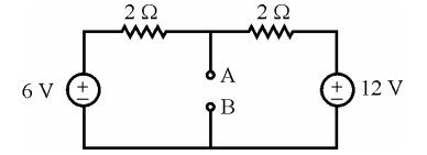
The Thevenin's equivalent across AB is
Read the following statements regarding Thevenin’s equivalent circuit :
(a) The Thevenin’s voltage is calculated across the short circuit terminals.
(b) The Thevenin’s voltage is calculated at the open circuit terminals.
(c) The connection in the circuit is open if any voltage source is present.
(d) The connection in the circuit is shorted if any voltage source is present.
Which of the above statements are incorrect ?
Consider the networks shown in the following figures (a) and (b) :

The above networks are :
Match the following :
List - I List - II (a) Superposition Theorem (i) Ratio between V and I is constant in different loops (b) Maximum Power Transfer Theorem (ii) Ideal current source with parallel Resistor (c) Norton's Theorem (iii) Load impedance is a complex conjugate (d) Reciprocity Theorem (iv) Not valid to Power of the circuit Codes :
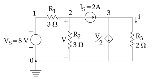
Find the value of i using the above circuit by making use of the superposition theorem.
Important Questions from Network Theorems
Which of the following statements is true?
- Which of the following is essential for reciprocity theorem to be applicable?
A linear element satisfies the property (ies) of:
Superposition theorem is only applicable for determining ____ only.
KVL gives the law of conservation of



