
In a single phase induction type energy meter, maximum torque is produced when the shunt magnetic flux:
Lags the supply voltage by 90 degrees
Understanding Energy Meter Torque Production
A single-phase induction type energy meter works based on the principle of electromagnetic induction. It has two main electromagnets: the shunt magnet and the series magnet. These magnets produce magnetic fluxes that interact with an aluminum disc, causing it to rotate. The speed of rotation of the disc is proportional to the power being consumed, and the total number of rotations over time indicates the total energy consumed.
Key Components and Fluxes
- Shunt Magnet: Connected across the supply voltage. It has a voltage coil with a large number of turns and is highly inductive. This magnet produces a magnetic flux (shunt flux, \(\Phi_s\)) proportional to the supply voltage.
- Series Magnet: Connected in series with the load. It has a current coil with a few turns. This magnet produces a magnetic flux (series flux, \(\Phi_{se}\)) proportional to the load current.
- Aluminum Disc: Placed between the air gaps of the shunt and series magnets. Eddy currents are induced in this disc due to the changing magnetic fluxes.
How Torque is Generated in an Induction Energy Meter
The driving torque that rotates the aluminum disc is produced by the interaction between the magnetic fluxes (\(\Phi_s\) and \(\Phi_{se}\)) and the eddy currents induced in the disc by the other flux. Specifically, the torque is primarily due to:
- Interaction of \(\Phi_s\) with the eddy currents induced by \(\Phi_{se}\).
- Interaction of \(\Phi_{se}\) with the eddy currents induced by \(\Phi_s\).
The total driving torque (\(T_d\)) is proportional to the product of the two fluxes and the sine of the phase angle between them. However, for accurate energy measurement, the torque needs to be proportional to the instantaneous power (\(VI \cos\phi\)).
Phase Relationship for Maximum Torque and Correct Operation
In an ideal induction type energy meter, the shunt flux (\(\Phi_s\)) produced by the voltage coil should lag the supply voltage (\(V\)) by exactly 90 degrees. The series flux (\(\Phi_{se}\)) produced by the current coil is nearly in phase with the load current (\(I\)).
Let's consider the ideal phase relationships:
- Supply Voltage: \(V\) at angle \(0^\circ\) (reference).
- Supply Current: \(I\) at angle \(-\phi\) (assuming lagging power factor, \(\phi\) is the power factor angle).
- Ideal Shunt Flux: \(\Phi_s\) lags \(V\) by \(90^\circ\), so \(\Phi_s\) is at angle \(-90^\circ\).
- Series Flux: \(\Phi_{se}\) is in phase with \(I\), so \(\Phi_{se}\) is at angle \(-\phi\).
The phase angle between the shunt flux (\(\Phi_s\)) and the series flux (\(\Phi_{se}\)) is \(\theta = (-\phi) - (-90^\circ) = 90^\circ - \phi\).
The driving torque is proportional to \(\Phi_s \Phi_{se} \sin(\text{angle between fluxes})\). For correct energy measurement, the torque should be proportional to \(VI \cos\phi\). The torque generated is actually proportional to \(\Phi_s \Phi_{se} \sin(90^\circ - \phi)\), which is proportional to \(\Phi_s \Phi_{se} \cos\phi\). Since \(\Phi_s \propto V\) and \(\Phi_{se} \propto I\), the torque is proportional to \(VI \cos\phi\), which is the instantaneous power.
To achieve the ideal \(90^\circ\) lag of the shunt flux behind the supply voltage, the voltage coil is designed to be highly inductive. Additionally, a compensating coil or an inductive shunt (known as the 'lag adjustment') is used on the shunt magnet to ensure this precise phase relationship.
While maximum torque between *any* two interacting fluxes for a given magnitude occurs when they are 90 degrees apart, in the context of an energy meter measuring power (\(VI \cos\phi\)), the crucial requirement for accurate registration is that the shunt flux lags the supply voltage by 90 degrees. This specific phase shift ensures the resulting torque is proportional to the true power.
Analyzing the Options
- Is in phase with the supply voltage: If \(\Phi_s\) is in phase with \(V\), the torque relationship will not result in proportionality to \(VI \cos\phi\).
- Lags the supply voltage by 45 degrees: This would also result in incorrect torque proportionality.
- Lags the supply voltage by 90 degrees: This is the ideal condition for an induction type energy meter to produce driving torque that is proportional to the power being measured (\(VI \cos\phi\)), leading to accurate energy registration.
- Leads the supply voltage by 90 degrees: This would cause the torque to act in the opposite direction or lead to incorrect measurement.
Therefore, maximum torque (in the sense of proper operation and proportionality to power) is produced when the shunt magnetic flux lags the supply voltage by 90 degrees.
Revision Table: Induction Energy Meter Phases
| Component/Parameter | Ideal Phase Relationship (Relative to Supply Voltage V) |
|---|---|
| Supply Voltage (V) | \(0^\circ\) (Reference) |
| Shunt Magnetic Flux (\(\Phi_s\)) | Lags V by \(90^\circ\) |
| Supply Current (I) | Lags V by \(\phi\) (Power factor angle) |
| Series Magnetic Flux (\(\Phi_{se}\)) | In phase with I (Lags V by \(\phi\)) |
| Angle between \(\Phi_s\) and \(\Phi_{se}\) | \(90^\circ - \phi\) |
Additional Information: Lag Adjustment
Achieving the exact 90-degree lag of the shunt flux behind the supply voltage is critical for the accuracy of an induction type energy meter. Since the voltage coil has resistance, the flux it produces naturally lags the voltage by slightly less than 90 degrees. To correct this, a lagging device or phase compensator is used. This is typically a copper shading band or a small compensating coil placed around the central limb of the shunt magnet. Adjusting this band or coil changes the phase of the shunt flux, allowing it to be precisely lagged by 90 degrees relative to the voltage, thus ensuring the torque is proportional to \(VI \cos\phi\) for all power factors.
Similar Questions
Current is measured using:
Which of the following is not true with respect to the ammeter & voltmeter?
Which of the following devices is used for measuring the speed of DC machines?
How many wattmeter elements are needed at minimum to measure the power of a 3-phase circuit?
Which of the expressions is true for the balanced condition of the following wheatstone bridge?
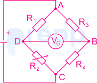
Wheatstone bridge can be used to measure ______.
Controlling Torque in megger is provided by:
High tonnage kettles are generally used in circulation lines with volumes up to _______?
A 60 microampere meter has a resistance of 100 ohms. If the meter has to measure 100 mA, then the value of current through the shunt is
Temperature control in bridge measurement is required because a difference in temperature will cause a difference in:
Important Questions from Measuring Instruments
Microscope is used for the study of which of the following?
What does a Vernier Caliper measure?
'Anemometer' is an instrument used for measuring the
Instrument used to observe changes in the solar system is :
The Windvane instrument measures the ______.



