
For an Emitter Bias BJT configuration arrange stability factor S(Iw) in descending order if β = 50. RB is base resistance and RE is emitter resistance. (A) RE = 0.1 RB Choose the most appropriate answer from the options given below :
(B) RB = 60 RE
(C) RB = 100 RE
(D) RE = 10 RB
(E) RB = 30 RE
(C), (B), (E), (A), (D)
The stability factor for emitter bias depends on one ratio only, so the five cases can be ranked by that ratio alone.
\(S=\dfrac{\left(1+\beta\right)\left(1+\dfrac{R_{B}}{R_{E}}\right)}{1+\beta+\dfrac{R_{B}}{R_{E}}}\)
Step 1 — express every case as the ratio k = RB/RE. Note that (A) and (D) are stated the other way round and must be inverted:
| Case | Given | k = RB/RE |
|---|---|---|
| (A) | RE = 0.1 RB | 10 |
| (B) | RB = 60 RE | 60 |
| (C) | RB = 100 RE | 100 |
| (D) | RE = 10 RB | 0.1 |
| (E) | RB = 30 RE | 30 |
Step 2 — evaluate with β = 50, so 1 + β = 51.
\(S=\dfrac{51\left(1+k\right)}{51+k}\)
| Case | k | S |
|---|---|---|
| (C) | 100 | \(\dfrac{51\times101}{151}=34.1\) |
| (B) | 60 | \(\dfrac{51\times61}{111}=28.0\) |
| (E) | 30 | \(\dfrac{51\times31}{81}=19.5\) |
| (A) | 10 | \(\dfrac{51\times11}{61}=9.2\) |
| (D) | 0.1 | \(\dfrac{51\times1.1}{51.1}=1.10\) |
Descending order is (C), (B), (E), (A), (D) — option 2.
Since S rises monotonically with k, no arithmetic is strictly needed: ranking the ratios 100, 60, 30, 10, 0.1 gives the answer directly. The two inversions in (A) and (D) are the only real trap, and (D) — a large emitter resistance against a small base resistance — is the best-biased case of the five.
What S means, and why small is good. It is defined as
\(S=\dfrac{\partial I_{C}}{\partial I_{CO}}\)
— how much the collector current moves for a given change in leakage. The ideal is \(S=1\), and case (D) very nearly reaches it. The two limits of the formula show the whole story: as \(k\to\infty\), S tends to \(1+\beta=51\), which is fixed bias, the worst possible; as \(k\to0\), S tends to 1, the best.
The design rule follows immediately : make \(R_{E}\) large compared with the Thevenin base resistance. The emitter resistor senses the collector current and feeds a correction back to the base-emitter loop, and the larger it is relative to \(R_{B}\), the more completely that correction acts.
Hence, the descending order is (C), (B), (E), (A), (D).
Similar Questions
Assertion (A) : A self-biased circuit has a better stability than a fixed bias circuit.
Reason (R) : It provides negative feed back by the use of an additional resistor between the base and ground.
The basic purpose of biasing a transistor with a network is
The quienscent state of transistor is when
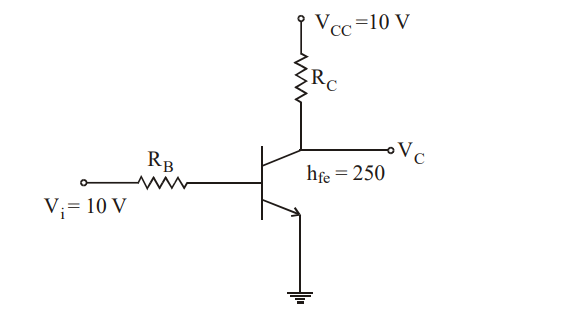
For a transistor inverter shown below, if IC sat is 10 mA, the value of RB and RC are
Assertion (A) : The bias instability occurs in transistors due to thermal variations.
Reason (R) : The reverse saturation current doubles for every 18 °C temperature rise. Due to this the reverse saturation current further heats the junction. As a result there is a thermal run-away.
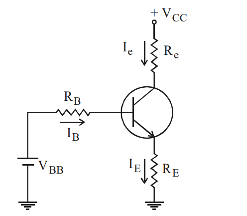
In a circuit given below the base current IB is
Assertion (A) : Completion of the design in a transistor requires the check of quiescent-point variations due to temperature changes and unit to unit parameter differences.
Reason (R) : As the principle of operation of the BJT & FET differ, so do the associated methods of Q-point stabilization.
Select your answer using the codes given below :
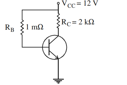
In a circuit shown below, the base current is
Important Questions from Biasing of Transistors
What is the operating point of a transistor as an amplifier known as?
When no ac input signals are connected to CE Transistor Load line can be plotted ______
In how many regions can the biased transistor work?
In a BJT, if the base-emitter junction is reverse-biased and the base-collector junction is reverse-biased, it is said to operate in
When transistors are used in digital circuits they usually operate in the:



