
A linear two terminal circuit can be replaced by an equivalent circuit consisting of a voltage source Vt in series with a resistor Rt where Rt is the ratio of 1. open circuit voltage to the short circuit current at the terminal pair.
2. short circuit current to the short circuit voltage at the terminal.
3. Open circuit voltage to the open circuit current at the terminal pair.
4. the independent sources are turned off.
1 and 4
Thevenin's theorem offers two equally valid routes to the same resistance, and statements 1 and 4 are exactly those two — option 1.
Method 1 — the ratio of the two extreme measurements (statement 1).
\(R_{Th}=\dfrac{V_{OC}}{I_{SC}}\)
Measure the voltage with the terminals open, then the current with them shorted; their ratio is the internal resistance. This works for any linear network, including one containing dependent sources.
Method 2 — deactivate the independent sources and look in (statement 4). Replace every independent voltage source by a short circuit (its internal resistance) and every independent current source by an open circuit, then compute the resistance seen from the terminals. This is usually the quicker route when the network is a plain resistive mesh.
| Source type | Replaced by | Why |
|---|---|---|
| Independent voltage source | Short circuit | An ideal one has zero internal resistance |
| Independent current source | Open circuit | An ideal one has infinite internal resistance |
| Dependent source | Left active | Its value is a response, not an input |
Statements 2 and 3 are self-contradictory. "Short circuit voltage" is zero by definition and "open circuit current" is zero by definition, so both ratios are meaningless — division by zero in one case and a guaranteed zero in the other. Only measurements taken at the two complementary extremes yield anything.
When the two methods diverge. If the network contains a controlled source, method 2 cannot be applied as it stands, because the dependent source stays active and there may be no independent source left to drive it. The usual fix is to apply a 1 V test source at the terminals and compute \(R_{Th}=V_{test}/I_{test}\), which is method 1 in another guise. It is also how an amplifier can show a Thevenin resistance far lower than any physical resistor inside it.
The practical value of the theorem is that a network of any complexity collapses to two numbers, so a load that varies — a potentiometer, a motor, a changing antenna impedance — can be analysed by hand for every setting.
Hence, the correct statements are 1 and 4.
Similar Questions
The Thevenin's equivalent across AB is
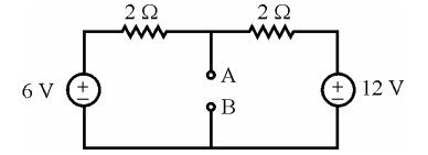
Which equivalent circuits are dual ?
For the n/w, find RTH

The principle of superposition is the property of
In Thevenin equivalent circuit which is incorrect :
Find out which of the following statements is wrong ?
The principle of superposition is useful for
Read the following statements regarding Thevenin’s equivalent circuit :
(a) The Thevenin’s voltage is calculated across the short circuit terminals.
(b) The Thevenin’s voltage is calculated at the open circuit terminals.
(c) The connection in the circuit is open if any voltage source is present.
(d) The connection in the circuit is shorted if any voltage source is present.
Which of the above statements are incorrect ?
Consider the networks shown in the following figures (a) and (b) :

The above networks are :
Match the following :
List - I List - II (a) Superposition Theorem (i) Ratio between V and I is constant in different loops (b) Maximum Power Transfer Theorem (ii) Ideal current source with parallel Resistor (c) Norton's Theorem (iii) Load impedance is a complex conjugate (d) Reciprocity Theorem (iv) Not valid to Power of the circuit Codes :
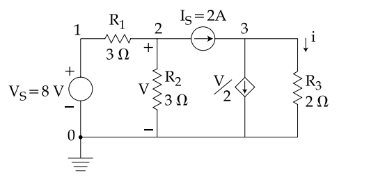
Find the value of i using the above circuit by making use of the superposition theorem.
Important Questions from Network Theorems
- Which of the following is essential for reciprocity theorem to be applicable?
A linear element satisfies the property (ies) of:
KVL gives the law of conservation of
The maximum power transfer theorem is used in
Millman’s theorem yields:



