
The phase locked loop (PLL) is one of the interesting applications of the lock-in amplifier. Apart from FM stereo decoders, tracking filters, motor speed control, FM demodulators, etc. it has found wide applications in generation of local oscillator frequencies in house-hold TV and FM tuners as automatic frequency control (AFC). Indeed, PLL has emerged as one of the fundamental building blocks in electronics and it is commercially available as a single package. Basically, a PLL is a lock-in amplifier in which the reference signal is provided by its own output, converted to frequency by a voltage controlled oscillator (VCO). When locked to the input frequency the dc output is small but sufficient to drive the VCO to produce a frequency which is equal to that of the signal. In this tracking situation, the input signal and the VCO output are almost in phase quadrature and the lock-in amplifier produces a small dc voltage which is often referred to as error voltage. The moment input signal is fed, the VCO frequency starts changing and the PLL is said to be in the capture mode. The VCO continues to change its frequency until it equals that of the input and stays there ; the PLL is then in the phase-locked state. In this state, if there is any change in the input frequency, the loop automatically tracks it through its repetitive action.
The sample and hold devices are used to perform :
Time-division-multiplexing
A sample-and-hold circuit takes a brief look at a signal and then freezes that value, and freezing values is exactly what lets several signals share one channel in turn. That is time-division multiplexing — option 3.
How the circuit works. A switch (usually a FET or CMOS gate) connects the input to a hold capacitor for a short sampling interval, charging it to the instantaneous input voltage. The switch then opens and the capacitor retains that voltage, buffered by a high-input-impedance follower so that nothing discharges it:
\(\text{Droop rate}=\dfrac{dV}{dt}=\dfrac{I_{leakage}}{C_{H}}\)
— the specification that decides how long the value stays valid.
Why TDM needs it. In a TDM system each channel is sampled in rotation and its sample occupies one time slot on the shared line. The sample must be held steady while the multiplexer, the ADC or the line driver does its work, and each channel's value must persist until that channel's turn comes round again. Without a hold, the value would be gone before it could be used. The sampling rate for each channel must satisfy Nyquist,
\(f_{s}\ge2f_{m}\)
so a system with N channels must run its commutator at \(Nf_{s}\).
| Multiplexing | Channels separated by | Key circuit |
|---|---|---|
| FDM | Different frequency bands | Modulators and band-pass filters |
| TDM | Different time slots | Sampler / commutator and sample-and-hold |
The other options are ruled out on function. FDM separates channels by shifting them to different frequencies, which needs mixers and filters, not a hold capacitor. Frequency and amplitude modulation are single-channel operations that alter a carrier's parameter continuously; neither requires a value to be frozen.
The other place a sample-and-hold is indispensable is at the input of an analog-to-digital converter. A SAR converter compares the input against its DAC output over n successive clock cycles, and the input must not move during that time — a change of even one LSB mid-conversion corrupts every bit still to be decided. Holding the sample makes the converted value correspond to one definite instant, which is also what makes the sampling time well defined for reconstruction.
Hence, sample-and-hold devices are used to perform time-division multiplexing.
Similar Questions
Time division multiplexing of digital signal ( Where Ai, Bi, Ci, Di represents respective bits of different channels, i = 1 to 4) given in the figure:
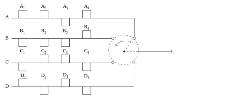
A. A1B1C1D1 (All channels have same bit rate)
B. A1A2B1B2C1D1C2D2 (All channels have same bit rate)
C. A1B1A2C1A3D1 (channel A bit rate is 3 times more than that of channels B, C, D)
D. A1B1C1A2D1 (channel A bit rate is 3-times more than that of channels B, C, D)
E. A1B1A2C1A3D1 (All channel have same bit rate)
Choose the correct answer from the options given below :
Assertion (A) : Signal multiplexing provides medium that allows large number of independent sources to share same physical channel.
Reason (R) : It is an aggregate information sent through time division multiplexing.
Important Questions from Time Division Multiplexing (TDM)
Time division multiplexing of digital signal ( Where Ai, Bi, Ci, Di represents respective bits of different channels, i = 1 to 4) given in the figure:
A. A1B1C1D1 (All channels have same bit rate)
B. A1A2B1B2C1D1C2D2 (All channels have same bit rate)
C. A1B1A2C1A3D1 (channel A bit rate is 3 times more than that of channels B, C, D)
D. A1B1C1A2D1 (channel A bit rate is 3-times more than that of channels B, C, D)
E. A1B1A2C1A3D1 (All channel have same bit rate)
Choose the correct answer from the options given below :
Assertion (A) : Signal multiplexing provides medium that allows large number of independent sources to share same physical channel.
Reason (R) : It is an aggregate information sent through time division multiplexing.
A voice signal band limited to 3.4 kHz is sampled at 8 kHz and pulse code modulated using 64 quantization levels. Ten such signals are time division multiplexed using on 5-bit synchronising word. The minimum channel band width will be
- A multiplexer combines four 100-Kbps channels using a time slot of 2 bits. What is the bit rate ?
- The main advantage of TDM over FDM is that it
TDM stands for Time Division Multiplexing
FDM stands for Frequency Division Multiplexing



