
The reading of an ac ammeter connected to a half controlled rectifier with firing angle α = 0 will be :
\(\dfrac{I_{m}}{\sqrt{2}}\)
Two facts settle this: what an AC ammeter reads, and what a half-controlled bridge does at zero firing angle.
An AC ammeter is an RMS-reading instrument. Moving-iron and thermal instruments respond to the heating effect, which depends on the mean square of the current, so whatever the waveform they indicate
\(I_{rms}=\sqrt{\dfrac{1}{T}\int_{0}^{T}i^{2}(t)\,dt}\)
At α = 0 the half-controlled bridge behaves as an uncontrolled one. The thyristors are fired the instant they become forward biased, so they conduct exactly as diodes would, and each half-cycle of the supply is passed to the load in turn. The AC-side current is therefore a complete sinusoid of peak Im — no part of it is chopped away.
The RMS value of a full sine wave is the standard result :
\(I_{rms}=\sqrt{\dfrac{1}{2\pi}\int_{0}^{2\pi}\left(I_{m}\sin\theta\right)^{2}d\theta}=\dfrac{I_{m}}{\sqrt{2}}=0.707\,I_{m}\)
which is option 2.
| Option | What it actually is |
|---|---|
| Im/2 | RMS of a half-wave rectified sine |
| Im/√2 | RMS of a full sine — correct |
| √2 Im | Dimensionally impossible — RMS can never exceed the peak |
| Im/2π | Not a standard value; resembles a mean rather than an RMS |
Option 3 can be discarded on sight: for any waveform the RMS value lies between zero and the peak, so a factor greater than one is impossible. Option 1 is the near miss for anyone who assumes only half the wave reaches the AC side — true for a half-wave circuit, but this is a bridge and both half-cycles are used.
What changes when α is increased. Each thyristor now conducts only from α to π, so the AC current becomes a chopped sinusoid and the RMS value falls:
\(I_{rms}(\alpha)=I_{m}\sqrt{\dfrac{1}{2\pi}\left(\pi-\alpha+\dfrac{\sin2\alpha}{2}\right)}\)
which reduces to \(I_{m}/\sqrt{2}\) at α = 0, confirming the answer.
Why the half-controlled bridge is used is that replacing two of the four thyristors with diodes halves the cost and the gate-drive complexity, and the resulting circuit cannot invert — it works in one quadrant only. Its freewheeling action also improves the input power factor compared with a fully controlled bridge at the same firing angle.
Hence, the ammeter reads Im/√2.
Similar Questions
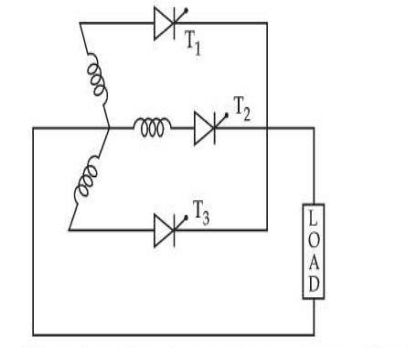
For the circuit given, phase voltage is Vm sin ωmt, where Vm is the peak phase voltage. The value of maximum average output voltage that occurs at a delay angle α = 0 is given by :
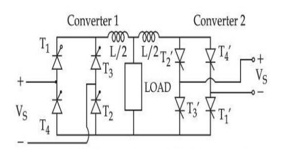
The above circuit is operated at 120 V – 60 Hz supply and the load resistance R = 20 Ω, L = 40 mH, delay angles are α1 = 60°, α2 = 120°. The value of :
(A) Peak circulating current = 11.250 A
(B) Peak circulating current = 6.250 A
(C) Peak current of converter 1 = 8.485 A
(D) Peak current of converter 1 = 19.735 AChoose the most appropriate answer from the options given below :
In a two quadrant single phase SCR Drive armature current becomes continuous when :
In one quadrant converters such as half controlled bridge circuit or single phase circuit with fly wheel diodes for DC moter.
In a fully controlled three phase bridge without fly wheel operation the displacement factor and power factor is :
Important Questions from Phase Controlled Rectifiers
- Which of the following is control element in Silicon Controlled Resistor (SCR)?
A 240 V single-phase AC supply is fed to a load resistor of 100 Ω through a thyristor. If the thyristor is fired at 90°, what is the power consumed by the load?
The maximum firing angle that can be obtained by a pure resistive trigger circuit used in phase control circuit is:
In a 3-phase converter circuit, during commutation when one SCR in one phase is turned on, turning of an SCR in another phase results is:
- Which mode is described when the anode is assigned a positive voltage, the gate is assigned a zero voltage disconnected and the cathode is assigned a negative voltage?



