
In phase control and Integral cycle control the supply voltage is ac and the armature voltage is rectified ac, where as in chopper control the supply is dc and the average armature voltage is proportional to the duty ratio of the chopper. The chopper system is used for dc traction & battery operated vehicle - Choppers using thyristors are more complicated than the phase control system. This is because an auxiliary commutation arrangement is necessary for choppers, whereas commutation is natural owing to a.c. supply in phase control or integral cycle control. Read the paragraph carefully and answer the question based on it.
In a fully controlled three phase bridge without fly wheel operation the displacement factor and power factor is :
\(\cos\alpha,\ \frac{3}{\pi}\cos\alpha\)
To determine the displacement factor and power factor of a fully controlled three-phase bridge rectifier without flywheel operation, we need to understand the relationship between the firing angle and these factors.
- The displacement factor is the cosine of the firing angle \(\alpha\). It represents the phase difference between the input voltage and the fundamental input current. Therefore, the displacement factor is given by:
- The power factor of the rectifier is affected by the extinction angle, but simplistically, for power factor calculation in rectifiers, we consider the fundamental component of the current. The power factor is the product of the displacement factor and the distortion factor (which comes from the harmonic content of the output current waveform).
- For a three-phase fully controlled bridge rectifier, the power factor can be expressed as:
- Considering the given options:
- Option 1: \(\cos\frac{\alpha}{2}, \sin 2\alpha\) - Incorrect because the forms do not match known formulas for phase control in rectifiers.
- Option 2: \(\cos\alpha, \frac{3}{\pi}\cos\alpha\) - Correct because this matches the standard formulas for displacement and power factor in fully controlled converters.
- Option 3: \(\cos(90-\alpha), \cos\alpha\) - Incorrect due to incorrect forms for controlled rectifiers.
- Option 4: \(\cos 2\alpha, \frac{1}{\pi}\cos 3\alpha\) - Incorrect since these are not standard forms for displacement and power factors.
- Therefore, the correct answer is:
Understanding these factors is crucial for analyzing the performance of rectifiers in power electronics and drives, especially concerning efficiency and effective control of power.
Similar Questions
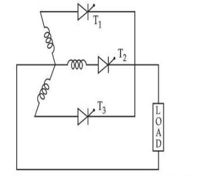
For the circuit given, phase voltage is Vm sin ωmt, where Vm is the peak phase voltage. The value of maximum average output voltage that occurs at a delay angle α = 0 is given by :
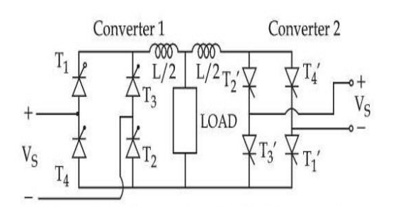
The above circuit is operated at 120 V – 60 Hz supply and the load resistance R = 20 Ω, L = 40 mH, delay angles are α1 = 60°, α2 = 120°. The value of :
(A) Peak circulating current = 11.250 A
(B) Peak circulating current = 6.250 A
(C) Peak current of converter 1 = 8.485 A
(D) Peak current of converter 1 = 19.735 AChoose the most appropriate answer from the options given below :
In a two quadrant single phase SCR Drive armature current becomes continuous when :
In one quadrant converters such as half controlled bridge circuit or single phase circuit with fly wheel diodes for DC moter.
The reading of an ac ammeter connected to a half controlled rectifier with firing angle α = 0 will be :
Important Questions from Phase Controlled Rectifiers
- Which of the following is control element in Silicon Controlled Resistor (SCR)?
A 240 V single-phase AC supply is fed to a load resistor of 100 Ω through a thyristor. If the thyristor is fired at 90°, what is the power consumed by the load?
The maximum firing angle that can be obtained by a pure resistive trigger circuit used in phase control circuit is:
In a 3-phase converter circuit, during commutation when one SCR in one phase is turned on, turning of an SCR in another phase results is:
- Which mode is described when the anode is assigned a positive voltage, the gate is assigned a zero voltage disconnected and the cathode is assigned a negative voltage?



