
For the circuit given, phase voltage is Vm sin ωmt, where Vm is the peak phase voltage. The value of maximum average output voltage that occurs at a delay angle α = 0 is given by :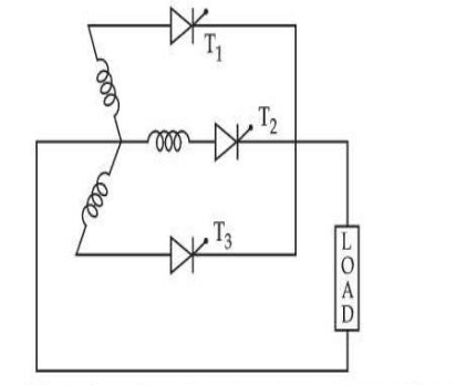
\(\dfrac{3\sqrt{3}\,V_{m}\cos\alpha}{2\pi}\)
For a three-phase half-wave controlled rectifier the average output is
\(V_{dc}=\dfrac{3\sqrt{3}\,V_{m}}{2\pi}\cos\alpha\)
— option 3.
The derivation. Each thyristor conducts for one third of a cycle, that is \(2\pi/3\) radians, and conduction begins at the delay angle \(\alpha\) measured from the natural commutation point, which for a three-phase supply lies 30° after the phase voltage's zero crossing. Averaging over one conduction interval:
\(V_{dc}=\dfrac{3}{2\pi}\int_{\frac{\pi}{6}+\alpha}^{\frac{5\pi}{6}+\alpha}V_{m}\sin\omega t\ d\left(\omega t\right)\)
\(=\dfrac{3V_{m}}{2\pi}\left[-\cos\omega t\right]_{\frac{\pi}{6}+\alpha}^{\frac{5\pi}{6}+\alpha}=\dfrac{3V_{m}}{2\pi}\left[\cos\left(\tfrac{\pi}{6}+\alpha\right)-\cos\left(\tfrac{5\pi}{6}+\alpha\right)\right]\)
The bracket simplifies with the identity \(\cos A-\cos B=2\sin\frac{A+B}{2}\sin\frac{B-A}{2}\) to \(2\cos\alpha\sin\frac{\pi}{3}=\sqrt{3}\cos\alpha\), giving
\(V_{dc}=\dfrac{3\sqrt{3}\,V_{m}}{2\pi}\cos\alpha\)
Checking the numerical value at α = 0.
\(V_{dc}=\dfrac{3\times1.732}{2\pi}V_{m}=0.827\,V_{m}\)
That is a sensible answer: the output must be less than the peak \(V_{m}\), since the rectifier only ever selects the largest of three sinusoids and averages it. Option 2 gives 1.65 Vm — twice the peak of the supply, which is impossible for a rectifier with no boosting element, and option 1 gives 0.55 Vm, the value for a single-phase circuit rather than three. Option 4 halves the correct answer.
Why the cosine appears. Delaying the firing by \(\alpha\) shifts the whole conduction window later, so it captures less of each sinusoid's crest — and the average falls exactly as \(\cos\alpha\). At \(\alpha=90^{\circ}\) the output is zero, and beyond it the average goes negative: with a highly inductive load the circuit then works as an inverter, returning power to the AC supply, which is the basis of regenerative braking in DC drives.
Why three phases are preferred. The output ripple is at three times the supply frequency instead of one, and its amplitude is far smaller, so the filtering needed is much lighter than for a single-phase circuit of the same rating.
Hence, Vdc = 3√3 Vm cosα / 2π.
Similar Questions
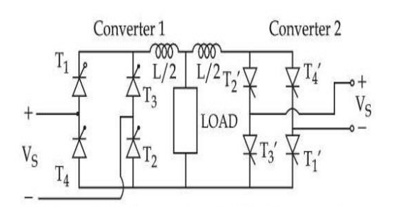
The above circuit is operated at 120 V – 60 Hz supply and the load resistance R = 20 Ω, L = 40 mH, delay angles are α1 = 60°, α2 = 120°. The value of :
(A) Peak circulating current = 11.250 A
(B) Peak circulating current = 6.250 A
(C) Peak current of converter 1 = 8.485 A
(D) Peak current of converter 1 = 19.735 AChoose the most appropriate answer from the options given below :
In a two quadrant single phase SCR Drive armature current becomes continuous when :
In one quadrant converters such as half controlled bridge circuit or single phase circuit with fly wheel diodes for DC moter.
The reading of an ac ammeter connected to a half controlled rectifier with firing angle α = 0 will be :
In a fully controlled three phase bridge without fly wheel operation the displacement factor and power factor is :
Important Questions from Phase Controlled Rectifiers
- Which of the following is control element in Silicon Controlled Resistor (SCR)?
A 240 V single-phase AC supply is fed to a load resistor of 100 Ω through a thyristor. If the thyristor is fired at 90°, what is the power consumed by the load?
The maximum firing angle that can be obtained by a pure resistive trigger circuit used in phase control circuit is:
In a 3-phase converter circuit, during commutation when one SCR in one phase is turned on, turning of an SCR in another phase results is:
- Which mode is described when the anode is assigned a positive voltage, the gate is assigned a zero voltage disconnected and the cathode is assigned a negative voltage?



