
Match the following lists : Codes :List – I List – II a. Voltage doubler i. 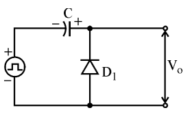
b. Halfwave rectifier ii. 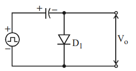
c. Positive clamping circuit iii. 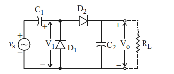
d. Negative clamping circuit iv. 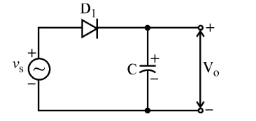
a-iii, b-iv, c-i, d-ii
To solve this problem, we need to match each item in List I with its corresponding circuit diagram in List II based on the characteristics and operation of the electronic circuits:
- Voltage Doubler: A voltage doubler is a circuit that converts an AC voltage to a DC voltage that is approximately twice the peak AC voltage. The circuit typically uses a combination of capacitors and diodes arranged to charge the capacitors in such a way that the output voltage is doubled. Looking at the provided diagrams:The above circuit uses two capacitors and diodes that can boost the input voltage, identifying it as a voltage doubler.
- Halfwave Rectifier: A halfwave rectifier allows one half (positive or negative) of an AC waveform to pass through and block the other half. This can be identified by looking for a single diode in the circuit:The diagram above shows a simple diode connected to AC input which allows only half of the waveform to pass through, identifying it as a halfwave rectifier.
- Positive Clamping Circuit: A positive clamping circuit shifts the entire input waveform upwards, so the minimum value of the waveform aligns with zero. It typically uses a diode and capacitor:The image above shows the circuit that shifts waveform upward using a diode connected to a capacitor, making it a positive clamping circuit.
- Negative Clamping Circuit: A negative clamping circuit shifts the whole input waveform downwards. The arrangement will be similar to positive clamping but reversed:This image shows the required configuration for a negative clamping circuit.
Thus, the correct match based on these explanations is: a-iii, b-iv, c-i, d-ii.
Similar Questions
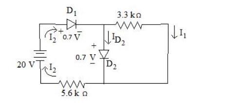
What current should flow through D2 diode? Consider the values given in circuit below.
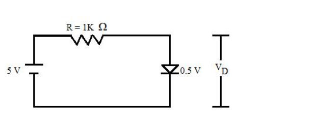
The diode used in fig. below has the threshold voltage of 0.5 V and a forward resistance of 4$\Omega$ Calculate the current flow ID through and the voltage drop VD across the diode.
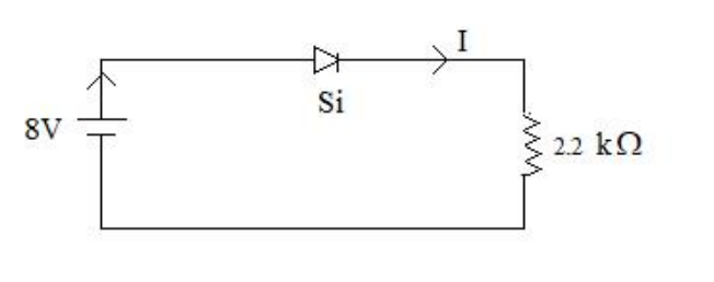
The value of current I flowing in the given circuit is:
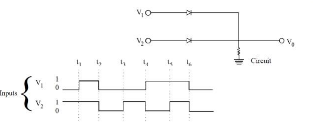
In the following circuit, for the given inputs V1 and V2, the correct option for output V0 is
Important Questions from Diodes and Its Applications - Teaching
What current should flow through D2 diode? Consider the values given in circuit below.
The diode used in fig. below has the threshold voltage of 0.5 V and a forward resistance of 4$\Omega$ Calculate the current flow ID through and the voltage drop VD across the diode.
- Assertion (A) : Clippers are networks that employ diodes to clip away a portion of an input signal without distorting the remaining part of the applied waveforms.
Reason (R) : In clipper circuit, the orientation of diode is very important and it decide the portion of the wave to be clipped. Clippers may be series or parallel type, depending upon the series/parallel connection of diode with the load. The value of current I flowing in the given circuit is:
In the following circuit, for the given inputs V1 and V2, the correct option for output V0 is



