
The value of current I flowing in the given circuit is: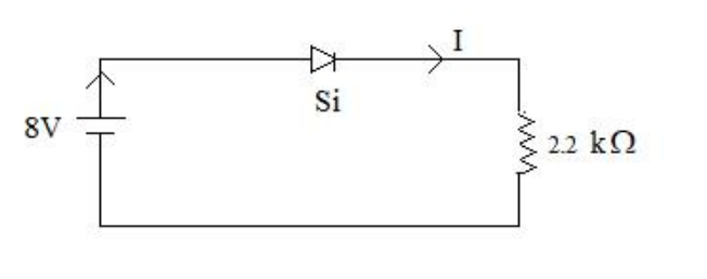
3.32 mA
Circuit. A single series loop: an 8 V d.c. source, a forward-biased silicon diode, and a 2.2 kΩ resistor. Because it is a series loop, the same current I flows through all three elements.
Model the diode. Use the piecewise-linear (constant-drop) model: once a conducting silicon diode is forward biased, its terminal voltage stays nearly fixed at the cut-in value
\(V_D \approx 0.7\ \text{V}\ (\text{Si}),\qquad V_D \approx 0.3\ \text{V}\ (\text{Ge})\)
Check the state first: the 8 V source pushes current into the anode, and 8 V is far above 0.7 V, so the diode is indeed ON and the model applies.
Apply KVL around the loop.
\(V_S = V_D + I R\)
Solve for the current.
\(I = \dfrac{V_S - V_D}{R}\)
Substitute the values \(V_S = 8\ \text{V}\), \(V_D = 0.7\ \text{V}\), \(R = 2.2\ \text{k}\Omega = 2200\ \Omega\):
\(I = \dfrac{8 - 0.7}{2200} = \dfrac{7.3}{2200}\)
\(I = 3.318 \times 10^{-3}\ \text{A} = 3.32\ \text{mA}\)
Where the other numbers come from — this is the useful lesson of the question. Each distractor corresponds to a different assumed diode drop:
Ideal diode (VD = 0): \(8/2200 = 3.63\ \text{mA}\). Germanium diode (VD = 0.3 V): \(7.7/2200 = 3.5\ \text{mA}\). A 1 V drop: \(7/2200 = 3.18\ \text{mA}\). Only the correct silicon value of 0.7 V gives 3.32 mA.
Takeaway. In any series diode–resistor problem, first confirm the diode is forward biased, then subtract its constant drop from the source voltage before dividing by the resistance; the material (Si or Ge) fixes which drop you subtract.
Hence, the current flowing in the circuit is 3.32 mA.
Similar Questions
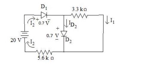
What current should flow through D2 diode? Consider the values given in circuit below.
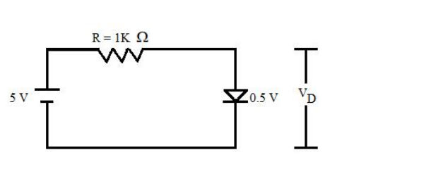
The diode used in fig. below has the threshold voltage of 0.5 V and a forward resistance of 4$\Omega$ Calculate the current flow ID through and the voltage drop VD across the diode.
Match the following lists :
List – I List – II a. Voltage doubler i. 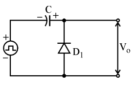
b. Halfwave rectifier ii. 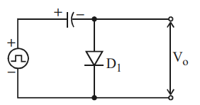
c. Positive clamping circuit iii. 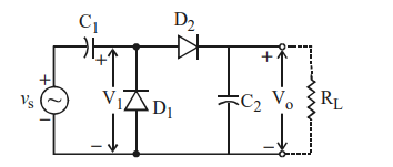
d. Negative clamping circuit iv. 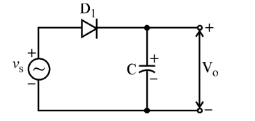
Codes :
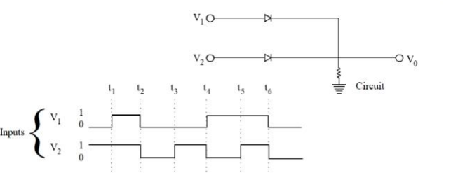
In the following circuit, for the given inputs V1 and V2, the correct option for output V0 is
Important Questions from Diodes and Its Applications - Teaching
What current should flow through D2 diode? Consider the values given in circuit below.
The diode used in fig. below has the threshold voltage of 0.5 V and a forward resistance of 4$\Omega$ Calculate the current flow ID through and the voltage drop VD across the diode.
Match the following lists :
List – I List – II a. Voltage doubler i. b. Halfwave rectifier ii. c. Positive clamping circuit iii. d. Negative clamping circuit iv. Codes :
- Assertion (A) : Clippers are networks that employ diodes to clip away a portion of an input signal without distorting the remaining part of the applied waveforms.
Reason (R) : In clipper circuit, the orientation of diode is very important and it decide the portion of the wave to be clipped. Clippers may be series or parallel type, depending upon the series/parallel connection of diode with the load. In the following circuit, for the given inputs V1 and V2, the correct option for output V0 is



