
What current should flow through D2 diode? Consider the values given in circuit below.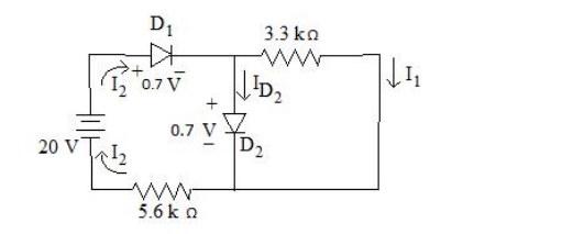
3.11 mA
Model each conducting diode as a constant 0.7 V drop (both are marked 0.7 V in the figure), then apply KVL and KCL.
Step 1 — the source loop through both diodes. Going round the 20 V source, D1, D2 and the 5.6 kΩ resistor:
\(20 = V_{D1} + V_{D2} + I_2 (5.6\ \text{k}\Omega)\)
\(20 = 0.7 + 0.7 + I_2(5600) \Rightarrow I_2 = \dfrac{18.6}{5600}\)
\(I_2 = 3.32\ \text{mA}\)
This I2 is the total current the source pushes into the junction node.
Step 2 — the current in the 3.3 kΩ branch. The 3.3 kΩ resistor is connected across the same two nodes as D2, so it sees the diode's forward drop:
\(I_1 = \dfrac{V_{D2}}{3.3\ \text{k}\Omega} = \dfrac{0.7}{3300} = 0.212\ \text{mA}\)
Step 3 — apply KCL at the junction. The incoming current I2 splits between the resistor branch and D2:
\(I_{D2} = I_2 - I_1 = 3.32 - 0.21\)
\(I_{D2} = 3.11\ \text{mA}\)
Why the method works. Because a conducting silicon diode clamps its terminals to about 0.7 V regardless of current, D2 fixes the node voltage; everything else then follows from Ohm's law and current division. Note that the 3.3 kΩ branch takes only 0.21 mA — a diode in parallel with a resistor carries the lion's share of the current, which is exactly how clamping and protection circuits work.
Check. 3.11 mA + 0.21 mA = 3.32 mA = I2, so KCL balances.
Hence, the current through D2 is 3.11 mA.
Similar Questions
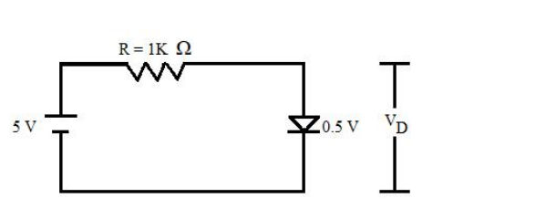
The diode used in fig. below has the threshold voltage of 0.5 V and a forward resistance of 4$\Omega$ Calculate the current flow ID through and the voltage drop VD across the diode.
Match the following lists :
List – I List – II a. Voltage doubler i. 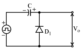
b. Halfwave rectifier ii. 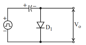
c. Positive clamping circuit iii. 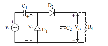
d. Negative clamping circuit iv. 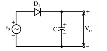
Codes :
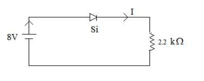
The value of current I flowing in the given circuit is:
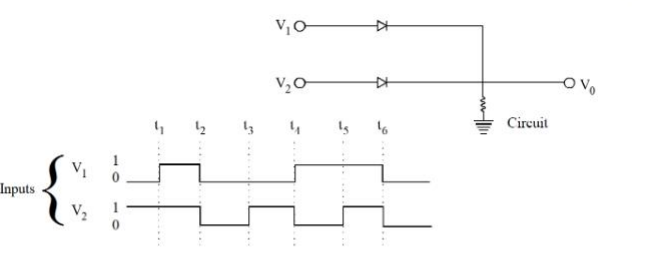
In the following circuit, for the given inputs V1 and V2, the correct option for output V0 is
Important Questions from Diodes and Its Applications - Teaching
The diode used in fig. below has the threshold voltage of 0.5 V and a forward resistance of 4$\Omega$ Calculate the current flow ID through and the voltage drop VD across the diode.
Match the following lists :
List – I List – II a. Voltage doubler i. b. Halfwave rectifier ii. c. Positive clamping circuit iii. d. Negative clamping circuit iv. Codes :
- Assertion (A) : Clippers are networks that employ diodes to clip away a portion of an input signal without distorting the remaining part of the applied waveforms.
Reason (R) : In clipper circuit, the orientation of diode is very important and it decide the portion of the wave to be clipped. Clippers may be series or parallel type, depending upon the series/parallel connection of diode with the load. The value of current I flowing in the given circuit is:
In the following circuit, for the given inputs V1 and V2, the correct option for output V0 is



