
The diode used in fig. below has the threshold voltage of 0.5 V and a forward resistance of 4$\Omega$ Calculate the current flow ID through and the voltage drop VD across the diode.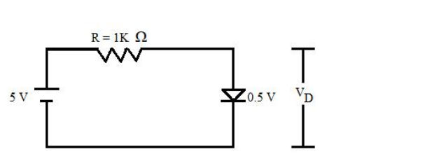
ID = 4.482 mA, VD = 0.52 V
Model the diode. The question gives two parameters, so use the piecewise-linear model: a conducting diode is represented by a battery equal to the threshold (cut-in) voltage Vγ in series with the forward (bulk) resistance rf.
\(V_\gamma = 0.5\ \text{V}, \qquad r_f = 4\ \Omega\)
Write KVL round the loop. The 5 V source drives the series combination of R = 1 kΩ and the diode model:
\(V_S = I_D R + V_\gamma + I_D r_f\)
Solve for the current.
\(I_D = \dfrac{V_S - V_\gamma}{R + r_f} = \dfrac{5 - 0.5}{1000 + 4} = \dfrac{4.5}{1004}\)
\(I_D = 4.482 \times 10^{-3}\ \text{A} = 4.482\ \text{mA}\)
Now the diode voltage. The drop across the device is the threshold plus the drop across its own bulk resistance:
\(V_D = V_\gamma + I_D r_f = 0.5 + (4.482\times10^{-3})(4)\)
\(V_D = 0.5 + 0.0179 = 0.5179 \approx 0.52\ \text{V}\)
Sanity checks. VD must be slightly larger than the 0.5 V threshold, never smaller — which immediately rules out the 0.45 V and 0.48 V options. And the resistor drop, \(4.482\ \text{mA}\times 1\ \text{k}\Omega = 4.482\ \text{V}\), plus 0.518 V returns the 5 V supply exactly.
Takeaway. With \(r_f \ll R\) the forward resistance barely affects the current (ignoring it gives 4.5 mA, only 0.4 % higher), but it is what makes the diode voltage rise above the threshold as the current increases. That small slope is the reciprocal of rf on the I-V characteristic.
Hence, ID = 4.482 mA and VD = 0.52 V.
Similar Questions
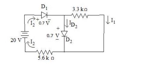
What current should flow through D2 diode? Consider the values given in circuit below.
Match the following lists :
List – I List – II a. Voltage doubler i. 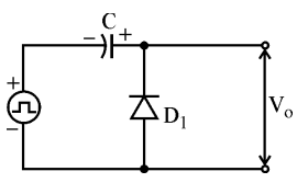
b. Halfwave rectifier ii. 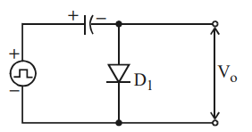
c. Positive clamping circuit iii. 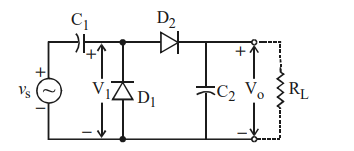
d. Negative clamping circuit iv. 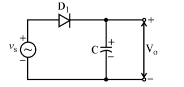
Codes :
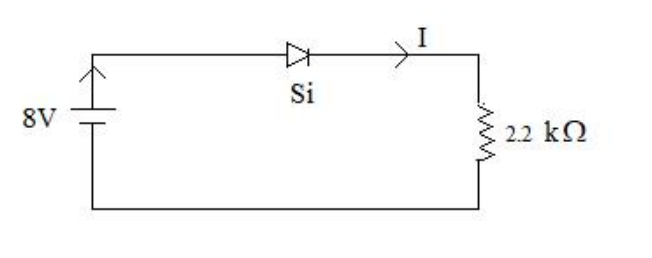
The value of current I flowing in the given circuit is:
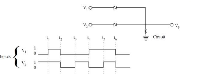
In the following circuit, for the given inputs V1 and V2, the correct option for output V0 is
Important Questions from Diodes and Its Applications - Teaching
What current should flow through D2 diode? Consider the values given in circuit below.
Match the following lists :
List – I List – II a. Voltage doubler i. b. Halfwave rectifier ii. c. Positive clamping circuit iii. d. Negative clamping circuit iv. Codes :
- Assertion (A) : Clippers are networks that employ diodes to clip away a portion of an input signal without distorting the remaining part of the applied waveforms.
Reason (R) : In clipper circuit, the orientation of diode is very important and it decide the portion of the wave to be clipped. Clippers may be series or parallel type, depending upon the series/parallel connection of diode with the load. The value of current I flowing in the given circuit is:
In the following circuit, for the given inputs V1 and V2, the correct option for output V0 is



