Consider a 3-bit counter, designed using T flip flops as shown below: Assume the initial state of the counter given by PQR as 000, what are the next three states?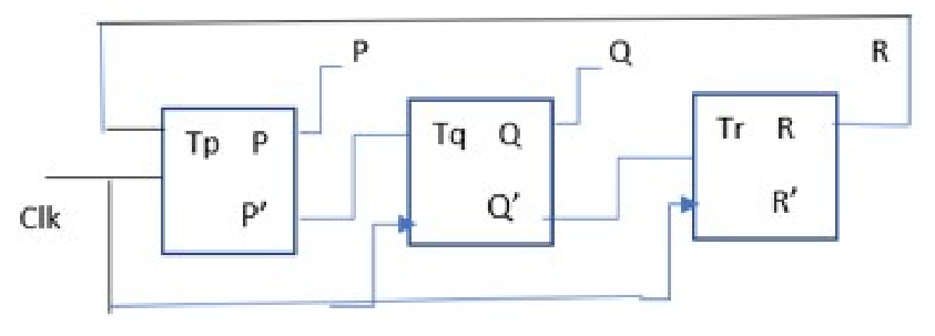
011, 101, 000
A T flip-flop toggles its output on the clock edge when T = 1 and holds it when T = 0, so Qnext = T ⊕ Q. In the circuit all three flip-flops share the clock, and the wiring read from the diagram is Tp = R (feedback from the last stage), Tq = P’ and Tr = Q’.
Step 1 — Simulate each clock edge from PQR = 000:
| Present PQR | Tp = R | Tq = P’ | Tr = Q’ | Next PQR |
|---|---|---|---|---|
| 000 | 0 | 1 | 1 | 011 |
| 011 | 1 | 1 | 0 | 101 |
| 101 | 1 | 0 | 1 | 000 |
Step 2 — From 000: P holds (Tp = 0), Q and R toggle, giving 011. From 011: P and Q toggle, R holds, giving 101. From 101: P and R toggle, Q holds, giving 000. The counter returns to its initial state after three clocks.
The sequences 001, 010, 111 and 001, 010, 000 are binary up-count patterns that ignore the feedback wiring, and 011, 101, 111 gets the third state wrong because with Tq = P’ = 0 at state 101 the Q output cannot toggle to 1.
011, 101, 000 option is correct.
Similar Questions
The number of flip-flops required to design a modulo - 272 counter is :
Match List - I with List - II.
List - I (Counter) List - II (uses/working) (A) N-bit Ring Counter (I) Uses universal clock (B) Synchronous Counter (II) Counts exactly N states (C) Asynchronous Counter (III) Counts 0 to 9 (D) Decimal Counter (IV) Main clock is applied to first flip-flop only Choose the correct answer from the options given below :
A binary 3-bit down counter uses J-K flip-flops, FFi with inputs Ji, Ki and outputs Qi, i = 0, 1, 2 respectively. The minimized expression for the input from following, is
I. J0 = K0 = 0
II. J0 = K0 = 1
III. J1 = K1 = Q0
IV. J1 = K1 = \(\overline{Q_0}\)
V. J2 = K2 = Q1 Q0
VI. J2 = K2 = \(\overline{Q_1}\,\overline{Q_0}\)
Important Questions from Counter
Which is not related to the counter circuit design?
A 16-bit synchronous binary up-counter is clocked with a frequency fCLK. The two most significant bits are OR-ed together to form an output Y. Measurements show that Y is periodic, and the duration for which Y remains high in each period is 24 ms. The clock frequency fCLK is ______ MHz. (Round off 2 decimal places.)
A MOD 2 and a MOD 5 up-counter when cascaded together results in a MOD ______ counter. (in integer)
A modulus 10 counter must have
How many flip-flops circuits are needed for a 4 bit counter?