In a parallel RLC circuit shown in figure at resonance A. Current I flows through the resistor B. Total current flowing through LC combination is zero C. Current flows in the inductor is zero D. total current flowing through LC combination is 2 A E. Current flows in the capacitor is zero Choose the most appropriate answer from the options given below : 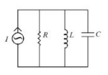
A and B only
Condition at resonance in a parallel RLC circuit. Resonance occurs when the inductive and capacitive susceptances cancel:
\(B_L=\dfrac{1}{\omega_0 L}=B_C=\omega_0 C \Rightarrow \omega_0=\dfrac{1}{\sqrt{LC}}\)
The L and C branches then present equal and opposite susceptances, so the parallel L–C pair has infinite impedance (an open circuit, ideally) and the total circuit impedance is purely resistive and maximum, equal to R.
B — "Total current through the LC combination is zero." TRUE. The inductor current lags the applied voltage by 90° while the capacitor current leads it by 90°, so the two are 180° apart; with equal magnitudes at ω0 their sum is zero:
\(I_L+I_C = \dfrac{V}{j\omega_0 L}+j\omega_0 CV = 0\)
A — "Current I flows through the resistor." TRUE. Since the L–C combination draws no net current from the source, the whole of the supply current is forced into R. This also means the circuit voltage is simply V = IR and the power factor is unity — the source delivers only real power.
C and E — "Current in the inductor is zero" / "current in the capacitor is zero." FALSE. This is the standard trap. Each branch individually carries a large current; only their sum vanishes. The two currents circulate round the L–C loop, with energy shuttling back and forth between the magnetic field of the coil and the electric field of the capacitor. Their magnitude is Q times the source current:
\(I_L=I_C=Q\,I, \qquad Q=R\sqrt{\dfrac{C}{L}}\)
which is why a parallel resonant circuit is called a tank circuit and why the branch currents can far exceed the line current — the reason for the name "current magnification".
D — "Total current through the LC combination is 2 A." FALSE. The net L–C current at resonance is zero, not 2 A, whatever the numerical values in the figure.
Hence, the correct answer is A and B only.
Similar Questions
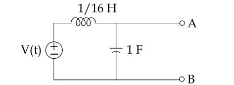
The circuit shown below, will act as an ideal current source with respect to terminals A and B when frequency is :
Important Questions from Electrical Resonance
The lower and upper cut-off frequencies are also called as _______ frequencies.
The circuit shown below, will act as an ideal current source with respect to terminals A and B when frequency is :
In RLC series circuit under variable frequency, what is initially negative and becomes zero and then positive?
Which of the following is NOT the property of a parallel resonant RLC circuit?
A tuned amplifier has a voltage gain of 100 and a bandwidth of 10 KHz at 500 KHz. It is required to increase the bandwidth to 20 KHz. This can be achieved by which one of the following ways?