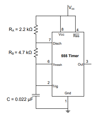
For Astable Multivibrator using IC 555, to increase the frequency of an astable 555 circuit without changing the duty cycle ratio, what should a designer do? Assume standard terminologies and resistor names.
Decrease the value of C while keeping resistors RA and RB constant
In the standard 555 timer astable multivibrator, the capacitor C charges through the series combination RA + RB and discharges through RB alone, producing a continuous train of pulses. Two design equations govern its behaviour:
Frequency: f = 1.44 / ((RA + 2RB) × C)
Duty cycle: D = (RA + RB) / (RA + 2RB)
The crucial observation is that frequency depends on both the resistors and the capacitor, but the duty cycle depends only on the resistor ratio — the capacitor C cancels out of the duty-cycle expression. This gives the designer a clean way to shift frequency without disturbing the pulse shape.
- Why decreasing C (with RA and RB fixed) is correct: reducing C makes the denominator (RA + 2RB) × C smaller, so f increases. Because C is absent from the duty-cycle formula and the resistors are unchanged, the duty cycle stays exactly the same. This meets both requirements — higher frequency, unchanged duty cycle.
- Increasing RA would raise the denominator and lower the frequency, and it would also change the resistor ratio, altering the duty cycle — so it fails on both counts.
- Increasing C moves the frequency in the wrong direction (it lowers f), so it cannot increase frequency.
- Decreasing the supply voltage does not appear in either formula (the charge/discharge thresholds scale with VCC), so it does not change the frequency or duty cycle in the ideal case.
Therefore, decreasing C while holding RA and RB constant is the right approach.
Similar Questions
Which internal component of the IC 555 is responsible for resetting the flip-flop when the voltage at Pin 6 exceeds two-thirds of Vcc supply?
In a monostable configuration of IC 555, why is the Discharge pin (Pin 7) connected directly to the Threshold pin (Pin 6)?
Important Questions from 555 Timer
What is the most popular IC used in timing circuits?
The control terminal (pin5) of 555 timer IC is normally connected to ground through a capacitor (∼ 0.01μF). This is to
Which internal component of the IC 555 is responsible for resetting the flip-flop when the voltage at Pin 6 exceeds two-thirds of Vcc supply?
In 555 astable multivibrator, R a= 22 k, R b= 39 K and C = 0.01 μf. Calculate the width of the positive pulse.
In the astable multivibrator circuit shown in the figure, the frequency of oscillation (in kHz) at the output pin 3 is _____________