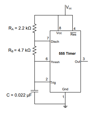
In 555 astable multivibrator, R a= 22 k, R b= 39 K and C = 0.01 μf. Calculate the width of the positive pulse.
0.423 ms
Calculating Pulse Width in a 555 Astable Multivibrator
The 555 timer IC is a versatile integrated circuit commonly used in various timer, pulse generation, and oscillator applications. When configured as an astable multivibrator, it produces a continuous output signal switching between a high and a low state, effectively generating a square or rectangular wave.
In the astable mode, the 555 timer's timing is determined by two external resistors, \(R_a\) and \(R_b\), and an external capacitor, \(C\). The output signal has a specific frequency and duty cycle, which are controlled by these components.
Understanding the 555 Astable Circuit Parameters
The key parameters for a 555 astable multivibrator are:
- \(R_a\): Resistance connected between the supply voltage (Vcc) and pin 7 (Discharge).
- \(R_b\): Resistance connected between pin 7 (Discharge) and pin 6 (Threshold) and pin 2 (Trigger).
- \(C\): Capacitor connected between pin 6 (Threshold) and pin 2 (Trigger) and ground.
- \(T_{high}\) (Pulse Width / ON Time): The duration for which the output is high.
- \(T_{low}\) (OFF Time): The duration for which the output is low.
- \(T\) (Period): The total time for one cycle (\(T = T_{high} + T_{low}\)).
- Frequency (\(f\)): The number of cycles per second (\(f = 1/T\)).
Formula for 555 Astable Pulse Width (\(T_{high}\))
The width of the positive pulse, or the ON time (\(T_{high}\)), for a 555 astable multivibrator is determined by the time it takes for the capacitor to charge from 1/3 Vcc to 2/3 Vcc through resistors \(R_a\) and \(R_b\). The formula is:
\(T_{high} = 0.693 \times (R_a + R_b) \times C\)
Where:
- \(R_a\) and \(R_b\) are in Ohms (\(\Omega\))
- \(C\) is in Farads (F)
- \(T_{high}\) is in seconds (s)
Step-by-Step Calculation of Pulse Width
We are given the following values for the 555 astable multivibrator:
- \(R_a = 22 \text{ k}\Omega\)
- \(R_b = 39 \text{ k}\Omega\)
- \(C = 0.01 \text{ }\mu\text{F}\)
First, convert the component values to their base units (Ohms and Farads):
- \(R_a = 22 \text{ k}\Omega = 22 \times 10^3 \Omega\)
- \(R_b = 39 \text{ k}\Omega = 39 \times 10^3 \Omega\)
- \(C = 0.01 \text{ }\mu\text{F} = 0.01 \times 10^{-6} \text{ F}\)
Now, plug these values into the formula for \(T_{high}\):
\(T_{high} = 0.693 \times (R_a + R_b) \times C\)
\(T_{high} = 0.693 \times (22 \times 10^3 \Omega + 39 \times 10^3 \Omega) \times 0.01 \times 10^{-6} \text{ F}\)
Sum the resistances:
\(R_a + R_b = (22 + 39) \times 10^3 \Omega = 61 \times 10^3 \Omega\)
Substitute the sum back into the \(T_{high}\) formula:
\(T_{high} = 0.693 \times (61 \times 10^3 \Omega) \times (0.01 \times 10^{-6} \text{ F})\)
Rearrange and calculate:
\(T_{high} = 0.693 \times 61 \times 0.01 \times 10^3 \times 10^{-6} \text{ s}\)
\(T_{high} = 0.693 \times 61 \times 0.01 \times 10^{-3} \text{ s}\)
\(T_{high} = 0.693 \times 0.61 \times 10^{-3} \text{ s}\)
\(T_{high} \approx 0.42273 \times 10^{-3} \text{ s}\)
Rounding the result to three significant figures, we get:
\(T_{high} \approx 0.423 \times 10^{-3} \text{ s}\)
Since \(10^{-3}\) seconds is equal to 1 millisecond (ms), the pulse width is:
\(T_{high} \approx 0.423 \text{ ms}\)
Result and Conclusion
The calculated width of the positive pulse (\(T_{high}\)) for the given 555 astable multivibrator circuit is approximately 0.423 ms.
Comparing this result with the provided options:
- 0.423 \(\mu\)s (0.423 \(\times 10^{-6}\) s)
- 0.423 ns (0.423 \(\times 10^{-9}\) s)
- 0.423 s
- 0.423 ms (0.423 \(\times 10^{-3}\) s)
The calculated value matches the option representing 0.423 ms.
Revision Table: 555 Astable Formulas
| Parameter | Formula | Notes |
|---|---|---|
| Positive Pulse Width (\(T_{high}\)) | \(0.693 \times (R_a + R_b) \times C\) | ON time, capacitor charges through \(R_a\) and \(R_b\) |
| Negative Pulse Width (\(T_{low}\)) | \(0.693 \times R_b \times C\) | OFF time, capacitor discharges through \(R_b\) |
| Period (\(T\)) | \(T_{high} + T_{low}\) or \(0.693 \times (R_a + 2R_b) \times C\) | Total time for one cycle |
| Frequency (\(f\)) | \(1/T\) or \(1.44 / ((R_a + 2R_b) \times C)\) | Number of cycles per second |
| Duty Cycle (%) | \((T_{high} / T) \times 100\%\) or \(((R_a + R_b) / (R_a + 2R_b)) \times 100\%\) | Percentage of time the output is high |
Additional Information: 555 Astable Multivibrator Operation
The 555 timer in astable mode constantly switches between two states, generating a free-running square wave. The operation relies on charging and discharging an external capacitor between 1/3 Vcc and 2/3 Vcc.
- When the capacitor voltage is below 1/3 Vcc, the internal comparator sets the flip-flop, making the output high and turning off the discharge transistor (pin 7). The capacitor charges through \(R_a\) and \(R_b\).
- When the capacitor voltage reaches 2/3 Vcc, the internal comparator resets the flip-flop, making the output low and turning on the discharge transistor. The capacitor discharges through \(R_b\) and the discharge pin (pin 7).
- When the capacitor voltage drops back down to 1/3 Vcc, the cycle repeats.
The values of \(R_a\), \(R_b\), and \(C\) directly control the charging and discharging times, thus determining the frequency and duty cycle of the output waveform. Note that \(R_a\) must not be zero, as this would short-circuit the power supply when the discharge transistor is on.
Important Questions from 555 Timer
What is the most popular IC used in timing circuits?
The control terminal (pin5) of 555 timer IC is normally connected to ground through a capacitor (∼ 0.01μF). This is to
For Astable Multivibrator using IC 555, to increase the frequency of an astable 555 circuit without changing the duty cycle ratio, what should a designer do? Assume standard terminologies and resistor names.
Which internal component of the IC 555 is responsible for resetting the flip-flop when the voltage at Pin 6 exceeds two-thirds of Vcc supply?
In the astable multivibrator circuit shown in the figure, the frequency of oscillation (in kHz) at the output pin 3 is _____________