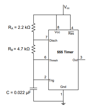
Which internal component of the IC 555 is responsible for resetting the flip-flop when the voltage at Pin 6 exceeds two-thirds of Vcc supply?
The Upper Comparator
The IC 555 timer contains an internal resistive voltage divider made of three equal resistors (each typically 5 kΩ) connected across the supply. This divider produces two fixed reference voltages: 1/3 Vcc and 2/3 Vcc. These references feed two internal comparators whose outputs drive an SR (Set-Reset) flip-flop, which in turn controls the output (Pin 3) and the discharge transistor (Pin 7).
The component that resets the flip-flop when Pin 6 (Threshold) exceeds 2/3 Vcc is the Upper Comparator:
- Its input compares the Threshold voltage at Pin 6 against the 2/3 Vcc reference from the divider.
- When the Pin 6 voltage rises above 2/3 Vcc, the Upper Comparator output goes HIGH.
- This HIGH signal RESETS the internal flip-flop, which turns the discharge transistor ON and drives the output LOW.
Why the other choices are wrong: the Lower Comparator does the opposite job — it monitors Pin 2 (Trigger) against 1/3 Vcc and SETS the flip-flop, so it cannot be responsible for resetting. The voltage divider network only generates the reference levels; it is a passive resistor chain and performs no comparison or switching. The discharge transistor is the output-side device that is switched ON after the flip-flop is reset — it is an effect of the reset action, not the cause of it.
Similar Questions
For Astable Multivibrator using IC 555, to increase the frequency of an astable 555 circuit without changing the duty cycle ratio, what should a designer do? Assume standard terminologies and resistor names.
In a monostable configuration of IC 555, why is the Discharge pin (Pin 7) connected directly to the Threshold pin (Pin 6)?
Important Questions from 555 Timer
What is the most popular IC used in timing circuits?
The control terminal (pin5) of 555 timer IC is normally connected to ground through a capacitor (∼ 0.01μF). This is to
For Astable Multivibrator using IC 555, to increase the frequency of an astable 555 circuit without changing the duty cycle ratio, what should a designer do? Assume standard terminologies and resistor names.
In 555 astable multivibrator, R a= 22 k, R b= 39 K and C = 0.01 μf. Calculate the width of the positive pulse.
In the astable multivibrator circuit shown in the figure, the frequency of oscillation (in kHz) at the output pin 3 is _____________