The tapping in an auto transformer is used to:
regulate voltage output
An auto transformer is a type of electrical transformer that uses a single winding to act as both the primary and the secondary winding, with a portion of the winding common to both. This type of transformer is widely used for various applications due to its efficiency and cost-effectiveness.
Let's analyze the options given:
- Reduce insulation: Although an autotransformer may use less insulation compared to a two-winding transformer for the same voltage level, the primary purpose of tapping in an autotransformer is not primarily to reduce insulation.
- Increase magnetic losses: No electrical device is designed with the purpose of increasing losses. In fact, transformers are generally designed to minimize losses.
- Regulate voltage output: This is the correct option. The primary purpose of having a tapping in an autotransformer is to adjust the voltage output. By changing the location of the tap on the winding, the number of turns and thus the voltage can be varied, allowing for control over the output voltage.
- Separate windings: In an autotransformer, the windings are not separate; they are partially common. Thus, tapping cannot be used to separate windings, which is a characteristic of traditional transformers with distinct primary and secondary windings.
Therefore, the correct answer is that the tapping in an auto transformer is used to regulate voltage output.
Similar Questions
- The curve obtained in the input characteristics of a BJT in common-emitter (CE) configuration is _______.
Which among the given statements correctly distinguishes Avalanche breakdown from Zener breakdown in a PN junction diode?
Important Questions from Zener Diodes
- A Zener diode is used as ________.
The value of zener current is
Zener diodes are used as _______.
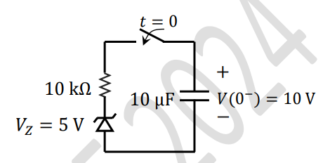
As shown in the circuit, the initial voltage across the capacitor is 10 V, with the switch being open. The switch is then closed at $t = 0$. The total energy dissipated in the ideal Zener diode ($V_Z = 5$ V) after the switch is closed (in mJ, rounded off to three decimal places) is _____________.
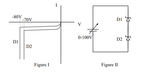
The I-V characteristics of the zener diodes D1 and D2 are shown in Figure I. These diodes are used in the circuit given in Figure II. If the supply voltage is varied from $0$ to $100 \ \text{V}$, then breakdown occurs in