
The I-V characteristics of the zener diodes D1 and D2 are shown in Figure I. These diodes are used in the circuit given in Figure II. If the supply voltage is varied from $0$ to $100 \ \text{V}$, then breakdown occurs in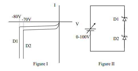
To solve this problem, we need to analyze the I-V characteristics of the zener diodes D1 and D2 shown in Figure I, and how they are used in the circuit shown in Figure II. The key point is to determine under which conditions each zener diode will enter breakdown when the supply voltage varies from 0 to 100 V.
The I-V characteristics in Figure I indicate the breakdown voltages of D1 and D2 as -80 V and -70 V respectively. In the circuit of Figure II, these zener diodes are connected in series with opposite polarities, and a variable supply voltage (V) is applied across them.
- The diode D1 has a breakdown voltage of \(-80 \ \text{V}\). It will enter the breakdown region when the reverse voltage across it exceeds 80 V.
- Similarly, diode D2 has a breakdown voltage of \(-70 \ \text{V}\). It will enter the breakdown region when the reverse voltage across it exceeds 70 V.
- When the supply voltage (V) reaches 80 V, diode D1 will experience the necessary reverse voltage to break down, as it is connected in reverse bias.
- For D2 to break down, the supply voltage needs to exceed 70 V. However, since D1 has a higher threshold of 80 V, it will conduct first when the supply voltage is between 70 V and 80 V.
- Once D1 is in breakdown at 80 V, it will maintain a constant reverse voltage across itself, preventing the further increase in voltage across D2.
- Thus, D2 will not reach its breakdown voltage because D1 has already started conducting.
Therefore, only D1 undergoes breakdown when the supply voltage varies from 0 to 100 V. This explains why the correct answer is D1 only.
Important Questions from Zener Diodes
The Zener resistance of a Zener diode, which exhibits 50 mV change in V zfor a 2.5 mA change in I zis _________.
The device used for voltage regulator is
Zener diode works under which region of V - I characteristics of the semiconductor diode?
IC LM309 Voltage regulator provides a fixed positive ______ output
In a linear IC voltage regulator, series pass transistor always operates in _____ region.


