An amount of charge Q passes through a coil of resistance R. If the current in the coil decreases to zero at a uniform rate during time T, then the amount of heat generated in the coil will be,
\(\dfrac{4Q^{2}R}{3T}\)
The charge that flows is the area under the current–time graph, while the Joule heat is the time integral of i2R. A current falling uniformly to zero is a straight line on the i–t graph.
Step 1 — Let the initial current be i0; then \(i(t)=i_{0}\left(1-\dfrac{t}{T}\right)\).
Step 2 — The charge is the triangular area: \(Q=\int_{0}^{T}i\,dt=\dfrac{i_{0}T}{2}\;\Rightarrow\;i_{0}=\dfrac{2Q}{T}\).
Step 3 — The heat produced is \(H=\int_{0}^{T}i^{2}R\,dt=i_{0}^{2}R\int_{0}^{T}\left(1-\dfrac{t}{T}\right)^{2}dt=\dfrac{i_{0}^{2}RT}{3}\).
Step 4 — Substituting i0: \(H=\dfrac{4Q^{2}}{T^{2}}\cdot\dfrac{RT}{3}=\dfrac{4Q^{2}R}{3T}\).
The expression with Q to the first power has the wrong dimensions for energy. Placing R in the denominator would mean that more resistance produces less heat for the same current, which is wrong. The product of the square of the charge with R and T is also dimensionally not an energy.
\(\dfrac{4Q^{2}R}{3T}\) option is correct.
Similar Questions
A charged particle of charge q and mass m is placed at a distance 2R from the centre of a vertical cylindrical region of radius R where magnetic field varies as \(\vec{B}=(4t^{2}-2t+6)\hat{k}\), where t is time. Then which of the following statement(s) is/are true ?
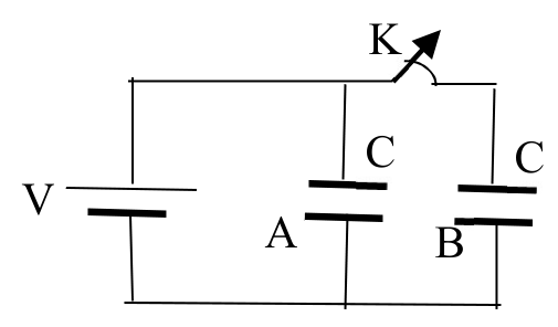
The figure shows two identical parallel plate capacitors A and B of capacitances C connected to a battery. The key K is initially closed. The switch is now opened and the free spaces between the plates of the capacitors are filled with a dielectric constant 3. Then which of the following statement(s) is/are true ?
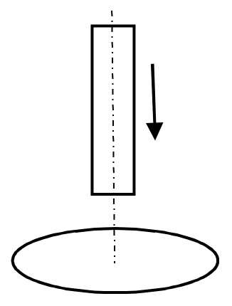
A bar magnet falls from rest under gravity through the centre of a horizontal ring of conducting wire as shown in figure. Which of the following graph best represents the speed (v) vs. time (t) graph of the bar magnet ?
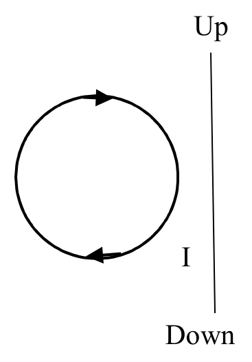
A circular coil is placed near a current carrying conductor, both lying on the plane of the paper. The current is flowing through the conductor in such a way that the induced current in the loop is clockwise as shown in the figure. The current in the wire is,
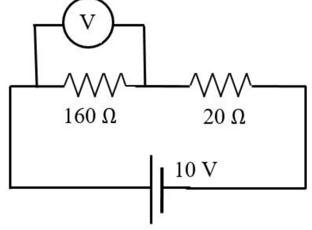
In an experiment on a circuit as shown in the figure, the voltmeter shows 8 V reading. The resistance of the voltmeter is,
A charged particle in a uniform magnetic field \(\vec{B} = B_0\hat{k}\) starts moving from the origin with velocity \(v = 3\hat{i} + 4\hat{k}\) m/s. The trajectory of the particle and the time t at which it reaches 2 m above x-y plane are,
An electric dipole of dipole moment \(\vec{p}\) is placed at the origin of the co-ordinate system along the z-axis. The amount of work required to move a charge ‘q’ from the point (a, 0, 0) to the point (0, 0, a) is,
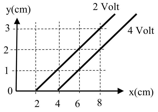
The figure represents two equipotential lines in x-y plane for an electric field. The x-component Ex of the electric field in space between these equipotential lines is,
A wire carrying a steady current I is kept in the x-y plane along the curve \(y = A\sin\left(\dfrac{2\pi}{\lambda}x\right)\).
A magnetic field B exists in the z-direction. The magnitude of the magnetic force in the portion of the wire between x = 0 and x = λ is
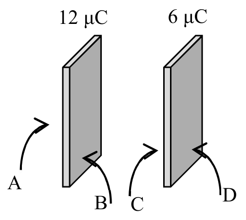
12 μC and 6 μC charges are given to the two conducting plates having same cross-sectional area and placed face to face close to each other as shown in the figure. The resulting charge distribution in μC on surfaces A, B, C and D are respectively,
Important Questions from Electricity and Magnetism
- A short bar magnet placed with its axis at $30^\circ$ with an external field of 800 Gauss, experiences a torque of 0.016 N.m. The work done in moving it from most stable to most unstable position is $\alpha \times 10^{-3} \text{ J}$. The value of $\alpha$ is ______.
- An electromagnetic wave of frequency $100\text{ MHz}$ propagates through a medium of conductivity, $\sigma = 10\text{ mho/m}$. The ratio of maximum conduction current density to maximum displacement current density is __________.
$\left[ \text{Take } \frac{1}{4\pi\varepsilon_0} = 9 \times 10^9\text{ Nm}^2\text{/C}^2 \right]$ - An inductor stores $16\text{ J}$ of magnetic field energy and dissipates $32\text{ W}$ of thermal energy due to its resistance when an a.c. current of $2\text{ A}$ (rms) and frequency $50\text{ Hz}$ flows through it. The ratio of inductive reactance to its resistance is _________. ($\pi = 3.14$)
- A simple pendulum made of mass 10 g and a metallic wire of length 10 cm is suspended vertically in a uniform magnetic field of 2 T. The magnetic field direction is perpendicular to the plane of oscillations of the pendulum. If the pendulum is released from an angle of $60^\circ$ with vertical, then maximum induced EMF between the point of suspension and point of oscillation is ___________ mV. (Take $g = 10\text{ m/s}^2$)
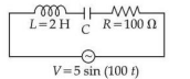
Using a variable frequency a.c. voltage source the maximum current measured in the given LCR circuit is 50 mA for $V = 5\sin(100t)$ The values of L and R are shown in the figure. The capacitance of the capacitor (C) used is ___________ $\mu\text{F}$.