Pendulum Induced EMF Calculation
This problem requires calculating the maximum induced electromotive force (EMF) in a simple pendulum moving within a uniform magnetic field.
Relevant Physics Concepts
When a conductor moves through a magnetic field, an EMF is induced across it. For a simple pendulum of length $L$ oscillating with maximum angular velocity $\omega_{max}$ in a magnetic field $B$ perpendicular to the plane of oscillation, the maximum induced EMF ($E_{max}$) is given by the formula:
$ E_{max} = \frac{1}{2} B L^2 \omega_{max} $
The maximum angular velocity ($\omega_{max}$) depends on the initial angle of release ($\theta_0$) and gravity ($g$).
Determining Maximum Angular Velocity ($\omega_{max}$)
Using conservation of energy, the potential energy lost when the pendulum swings from its highest point (angle $\theta_0$) to the lowest point (angle $0^\circ$) is converted into kinetic energy. The relationship is:
$ mgL(1 - \cos\theta_0) = \frac{1}{2} I \omega_{max}^2 $
For a simple pendulum where $I = mL^2$ (moment of inertia), this simplifies to:
$ \omega_{max}^2 = \frac{2g(1 - \cos\theta_0)}{L} $
Step-by-Step Solution
-
Gather Given Values:
- Magnetic field strength, $B = 2 \text{ T}$
- Pendulum wire length, $L = 10 \text{ cm} = 0.1 \text{ m}$
- Initial angle, $\theta_0 = 60^\circ$
- Acceleration due to gravity, $g = 10 \text{ m/s}^2$
- Mass $m = 10 \text{ g}$ (Note: mass is not required for this calculation)
-
Calculate $(1 - \cos\theta_0)$:
$ 1 - \cos(60^\circ) = 1 - \frac{1}{2} = 0.5 $
-
Calculate $\omega_{max}^2$:
$ \omega_{max}^2 = \frac{2 \times 10 \text{ m/s}^2 \times 0.5}{0.1 \text{ m}} = \frac{10}{0.1} = 100 \text{ (rad/s)}^2 $
-
Find $\omega_{max}$:
$ \omega_{max} = \sqrt{100} = 10 \text{ rad/s} $
-
Calculate Maximum Induced EMF ($E_{max}$):
Substitute the values into the EMF formula:
$ E_{max} = \frac{1}{2} \times (2 \text{ T}) \times (0.1 \text{ m})^2 \times (10 \text{ rad/s}) $
$ E_{max} = 1 \times 0.01 \times 10 = 0.1 \text{ V} $
-
Convert Voltage to Millivolts:
$ E_{max} = 0.1 \text{ V} \times \frac{1000 \text{ mV}}{1 \text{ V}} = 100 \text{ mV} $
The maximum induced EMF is 100 mV.
Similar Questions
- A short bar magnet placed with its axis at $30^\circ$ with an external field of 800 Gauss, experiences a torque of 0.016 N.m. The work done in moving it from most stable to most unstable position is $\alpha \times 10^{-3} \text{ J}$. The value of $\alpha$ is ______.
- An electromagnetic wave of frequency $100\text{ MHz}$ propagates through a medium of conductivity, $\sigma = 10\text{ mho/m}$. The ratio of maximum conduction current density to maximum displacement current density is __________.
$\left[ \text{Take } \frac{1}{4\pi\varepsilon_0} = 9 \times 10^9\text{ Nm}^2\text{/C}^2 \right]$ - An inductor stores $16\text{ J}$ of magnetic field energy and dissipates $32\text{ W}$ of thermal energy due to its resistance when an a.c. current of $2\text{ A}$ (rms) and frequency $50\text{ Hz}$ flows through it. The ratio of inductive reactance to its resistance is _________. ($\pi = 3.14$)
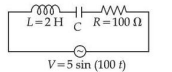
Using a variable frequency a.c. voltage source the maximum current measured in the given LCR circuit is 50 mA for $V = 5\sin(100t)$ The values of L and R are shown in the figure. The capacitance of the capacitor (C) used is ___________ $\mu\text{F}$.
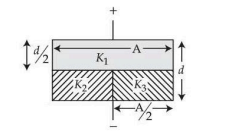
The space between the plates of a parallel plate capacitor of capacitance C (without any dielectric) is now filled with three dielectric slabs of dielectric constants $K_1 = 2$, $K_2 = 3$ and $K_3 = 5$ (as shown in figure). If new capacitance is $\frac{n}{3}C$ then the value of $n$ is ___________.
- The equation of the electric field of an electromagnetic wave propagating through free space is given by : $E = \sqrt{377} \sin(6.27 \times 10^3 t - 2.09 \times 10^{-5} x)\text{ N/C}$
The average power of the electromagnetic wave is $\left(\frac{1}{\alpha}\right)\text{ W/m}^2$. The value of $\alpha$ is ___________.
$\left[ \text{Take } \sqrt{\frac{\mu_0}{\epsilon_0}} = 377\text{ in SI units} \right]$ Combination of four parallel plate air capacitors is shown in figure. Separation between the plate P1 & P2 is $\frac{d}{3}$ and separation between the plates P2 and P3 is d.
The equivalent capacitance of the configuration is _____________$\mu$F.
(Given $\frac{\epsilon_0 A}{d} = 4\mu$F . Where A=Area of plates)
- A plane polarized monochromatic EM wave is traveling in vacuum along z direction such that at $t = t_1$ it is found that the electric field is zero at a spatial point $z_1$. The next zero that occurs in its neighbourhood is at $z_2$. The frequency of the electromagnetic wave is :
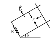
A copper rod of mass m slides under gravity on two smooth parallel rails, with separation $l$ and set at an angle of $\theta$ with the horizontal. At the bottom, rails are joined by a resistance R. There is a uniform magnetic field B normal to the plane of the rails, as shown in the figure. The terminal speed of the copper rod is :
- A copper rod of cross-sectional area A carries a uniform current I through it. At temperature T, if the volume charge density of the rod is $\rho$, how long will the charges take to travel a distance d?
Important Questions from Electricity and Magnetism
- A short bar magnet placed with its axis at $30^\circ$ with an external field of 800 Gauss, experiences a torque of 0.016 N.m. The work done in moving it from most stable to most unstable position is $\alpha \times 10^{-3} \text{ J}$. The value of $\alpha$ is ______.
- An electromagnetic wave of frequency $100\text{ MHz}$ propagates through a medium of conductivity, $\sigma = 10\text{ mho/m}$. The ratio of maximum conduction current density to maximum displacement current density is __________.
$\left[ \text{Take } \frac{1}{4\pi\varepsilon_0} = 9 \times 10^9\text{ Nm}^2\text{/C}^2 \right]$ - An inductor stores $16\text{ J}$ of magnetic field energy and dissipates $32\text{ W}$ of thermal energy due to its resistance when an a.c. current of $2\text{ A}$ (rms) and frequency $50\text{ Hz}$ flows through it. The ratio of inductive reactance to its resistance is _________. ($\pi = 3.14$)
Using a variable frequency a.c. voltage source the maximum current measured in the given LCR circuit is 50 mA for $V = 5\sin(100t)$ The values of L and R are shown in the figure. The capacitance of the capacitor (C) used is ___________ $\mu\text{F}$.
The space between the plates of a parallel plate capacitor of capacitance C (without any dielectric) is now filled with three dielectric slabs of dielectric constants $K_1 = 2$, $K_2 = 3$ and $K_3 = 5$ (as shown in figure). If new capacitance is $\frac{n}{3}C$ then the value of $n$ is ___________.