A bar magnet falls from rest under gravity through the centre of a horizontal ring of conducting wire as shown in figure. Which of the following graph best represents the speed (v) vs. time (t) graph of the bar magnet ?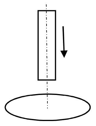
A magnet moving relative to a conducting ring changes the magnetic flux through the ring, so an emf and a current are induced. By Lenz's law the induced current always opposes the relative motion, which means the ring exerts a retarding magnetic force on the falling magnet.
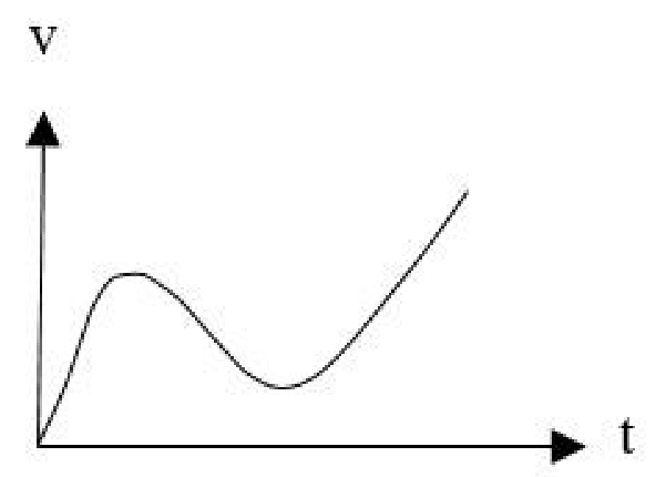
Step 1 — Released from rest far above the ring, the magnet speeds up under gravity, so the graph starts at zero and rises.
Step 2 — Close to the ring the flux changes fastest; the opposing force grows large and can exceed the weight, so the speed passes a maximum and falls while the magnet goes through the ring (on both the approach and the exit the induced current resists the motion).
Step 3 — Once the magnet is well below the ring the rate of change of flux becomes negligible, the magnetic force vanishes and the magnet falls freely with acceleration g, so the speed rises steadily along a nearly straight line.
A curve that flattens out to a constant speed would need a drag that keeps acting all along the fall, as in a long conducting tube, not a single ring. A curve that drops back to zero speed would mean the magnet comes to rest, which cannot happen because the induced force exists only while the magnet moves. A curve that begins at a non-zero speed contradicts the release from rest.
A curve that rises, dips near the ring and then rises steadily option is correct.
Similar Questions
A charged particle of charge q and mass m is placed at a distance 2R from the centre of a vertical cylindrical region of radius R where magnetic field varies as \(\vec{B}=(4t^{2}-2t+6)\hat{k}\), where t is time. Then which of the following statement(s) is/are true ?
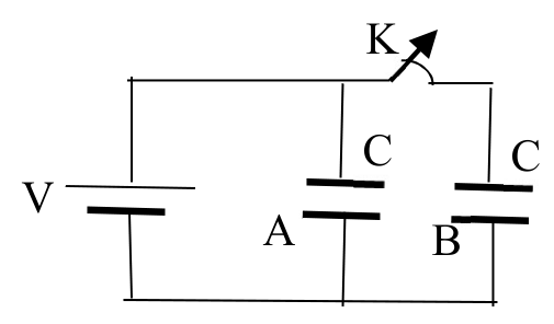
The figure shows two identical parallel plate capacitors A and B of capacitances C connected to a battery. The key K is initially closed. The switch is now opened and the free spaces between the plates of the capacitors are filled with a dielectric constant 3. Then which of the following statement(s) is/are true ?
An amount of charge Q passes through a coil of resistance R. If the current in the coil decreases to zero at a uniform rate during time T, then the amount of heat generated in the coil will be,
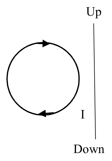
A circular coil is placed near a current carrying conductor, both lying on the plane of the paper. The current is flowing through the conductor in such a way that the induced current in the loop is clockwise as shown in the figure. The current in the wire is,
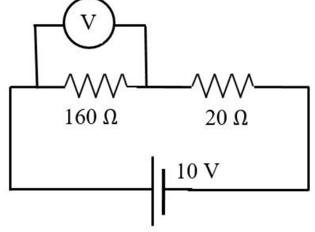
In an experiment on a circuit as shown in the figure, the voltmeter shows 8 V reading. The resistance of the voltmeter is,
A charged particle in a uniform magnetic field \(\vec{B} = B_0\hat{k}\) starts moving from the origin with velocity \(v = 3\hat{i} + 4\hat{k}\) m/s. The trajectory of the particle and the time t at which it reaches 2 m above x-y plane are,
An electric dipole of dipole moment \(\vec{p}\) is placed at the origin of the co-ordinate system along the z-axis. The amount of work required to move a charge ‘q’ from the point (a, 0, 0) to the point (0, 0, a) is,
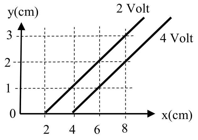
The figure represents two equipotential lines in x-y plane for an electric field. The x-component Ex of the electric field in space between these equipotential lines is,
A wire carrying a steady current I is kept in the x-y plane along the curve \(y = A\sin\left(\dfrac{2\pi}{\lambda}x\right)\).
A magnetic field B exists in the z-direction. The magnitude of the magnetic force in the portion of the wire between x = 0 and x = λ is
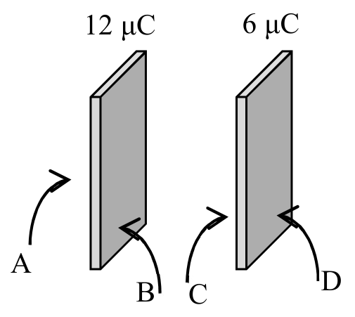
12 μC and 6 μC charges are given to the two conducting plates having same cross-sectional area and placed face to face close to each other as shown in the figure. The resulting charge distribution in μC on surfaces A, B, C and D are respectively,
Important Questions from Electricity and Magnetism
- A short bar magnet placed with its axis at $30^\circ$ with an external field of 800 Gauss, experiences a torque of 0.016 N.m. The work done in moving it from most stable to most unstable position is $\alpha \times 10^{-3} \text{ J}$. The value of $\alpha$ is ______.
- An electromagnetic wave of frequency $100\text{ MHz}$ propagates through a medium of conductivity, $\sigma = 10\text{ mho/m}$. The ratio of maximum conduction current density to maximum displacement current density is __________.
$\left[ \text{Take } \frac{1}{4\pi\varepsilon_0} = 9 \times 10^9\text{ Nm}^2\text{/C}^2 \right]$ - An inductor stores $16\text{ J}$ of magnetic field energy and dissipates $32\text{ W}$ of thermal energy due to its resistance when an a.c. current of $2\text{ A}$ (rms) and frequency $50\text{ Hz}$ flows through it. The ratio of inductive reactance to its resistance is _________. ($\pi = 3.14$)
- A simple pendulum made of mass 10 g and a metallic wire of length 10 cm is suspended vertically in a uniform magnetic field of 2 T. The magnetic field direction is perpendicular to the plane of oscillations of the pendulum. If the pendulum is released from an angle of $60^\circ$ with vertical, then maximum induced EMF between the point of suspension and point of oscillation is ___________ mV. (Take $g = 10\text{ m/s}^2$)
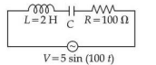
Using a variable frequency a.c. voltage source the maximum current measured in the given LCR circuit is 50 mA for $V = 5\sin(100t)$ The values of L and R are shown in the figure. The capacitance of the capacitor (C) used is ___________ $\mu\text{F}$.