Given Electrical Parameters
The problem provides the following values:
- Battery Electromotive Force (emf), $\mathcal{E} = 12 \text{ V}$
- Internal Resistance, $r = 2 \ \Omega$
- Circuit Current, $I = 0.6 \text{ A}$
Formula for Terminal Voltage
The terminal voltage ($V_T$) of a battery is the actual voltage across its terminals when current is flowing. It can be calculated using the formula:
$ V_T = \mathcal{E} - Ir $
Where:
- $V_T$ is the terminal voltage
- $\mathcal{E}$ is the battery emf
- $I$ is the current flowing through the circuit
- $r$ is the internal resistance of the battery
Calculation of Terminal Voltage
Substitute the given values into the formula:
$ V_T = 12 \text{ V} - (0.6 \text{ A} \times 2 \ \Omega) $
First, calculate the voltage drop across the internal resistance:
$ I \times r = 0.6 \text{ A} \times 2 \ \Omega = 1.2 \text{ V} $
Now, subtract this voltage drop from the battery's emf:
$ V_T = 12 \text{ V} - 1.2 \text{ V} $
$ V_T = 10.8 \text{ V} $
Result
The terminal voltage of the battery is $10.8 \text{ V}$.
Similar Questions
A 100-turn closely wound circular coil of radius $10 \text{ cm}$ has a magnetic field of $3.14 \times 10^{-3} \text{ T}$ at its centre. The current passing through the coil, and the magnitude of the magnetic moment of this coil are, respectively :
(Take $\mu_0 = 4\pi \times 10^{-7} \text{ T m/A}$)- An ac circuit contains a resistance of $1 \text{ k}\Omega$, a capacitor of $0.1 \ \mu\text{F}$ and an inductor of $1 \text{ mH}$ connected in series. The resonance frequency of the circuit is approximately :
- Two statements are given below :
A. When the forward bias voltage across a p-n junction diode increases above a certain threshold voltage, the diode current increases significantly.
B. This current is called reverse saturation current.
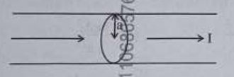
Choose the correct answer from the options given below : The figure given below shows a long straight solid wire of circular cross-section of radius 'a' carrying steady current I. The current I is uniformly distributed across its cross-section. The plot which correctly represents the variation of magnetic field (B) with distance (r) from the axis of the conductor in the region is :
Five capacitors of capacitances $C_1 = C_2 = C_3 = C_4 = 10 \ \mu\text{F}$ and $C_5 = 2.5 \ \mu\text{F}$ are connected as shown along with a battery of $50 \text{ V}$.
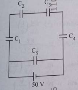
The equivalent capacitance and the charges on each capacitor respectively are :- A room heater is rated $400 \text{ W}, 220 \text{ V}$. If the supply voltage drops to $200 \text{ V}$, what will be the power consumed (approximately) ?
- The peak value of an alternating current is $5 \text{ A}$ and frequency is $60 \text{ Hz}$. How long will the current, starting from zero, take to reach the peak value ?
- Which of the following statements are correct ?
A. Inside a conductor the electrostatic field is zero.
B. Electric field at the surface of a charged conductor does not depend on its surface charge density.
C. The interior of a charged conductor can have no excess charge in the static situation.
D. At the surface of a charged conductor, the electrostatic field must be normal to the surface at every point.
E. The electrostatic potential is zero everywhere inside the charged conductor.
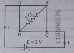
Choose the correct answer from the options given below : A uniform metallic wire having resistance $4 \ \Omega$ is bent to form a square loop ABCD. A resistance of $2 \ \Omega$ is connected between points B and D and a battery of $2 \text{ V}$ is connected across points A and C as shown in the figure. Now the value of current (I) is :
Match List I with List II :
List I (Electromagnetic wave) List II (Production) A. Microwave I. Electrons in atoms emit light when they move from a higher energy level to a lower energy level B. Visible light II. Radioactive decay of nucleus C. Gamma rays III. Vibration of atoms and molecules D. Infra-red ray IV. Klystron valve or magnetron valve
Choose the correct answer from the options given below :
Important Questions from Electricity and Magnetism
- The electric field of a plane electromagnetic wave, travelling in an unknown non-magnetic medium is given by,
$E_y = 20 \sin(3 \times 10^6 x - 4.5 \times 10^{14} t) \text{ V/m}$
(where x, t and other values have S.I. units). The dielectric constant of the medium is _________.
(speed of light in free space is $3 \times 10^8 \text{ m/s}$) - A conducting circular loop is rotated about its diameter at a constant angular speed of 100 rad/s in a magnetic field of 0.5 T perpendicular to the axis of rotation. When the loop is rotated by $30^\circ$ from the horizontal position, the induced EMF is 15.4 mV. The radius of the loop is _________ mm.
$\left(\text{Take } \pi = \frac{22}{7}\right)$ - A cylindrical conductor of length 2 m and area of cross-section $0.2 \text{ mm}^2$ carries an electric current of 1.6 A when its ends are connected to a 2 V battery. Mobility of electrons in the conductor is $\alpha \times 10^{-3} \text{ m}^2\text{/V.s}$. The value of $\alpha$ is :
(electron concentration $= 5 \times 10^{28} \text{/m}^3$ and electron charge = $1.6 \times 10^{-19} \text{ C}$) - A short bar magnet placed with its axis at $30^\circ$ with an external field of 800 Gauss, experiences a torque of 0.016 N.m. The work done in moving it from most stable to most unstable position is $\alpha \times 10^{-3} \text{ J}$. The value of $\alpha$ is ______.
- A regular hexagon is formed by six wires each of resistance $r \text{ }\Omega$ and the corners are joined to the centre by wires of same resistance. If the current enters at one corner and leaves at the opposite corner, the equivalent resistance of the hexagon between the two opposite corners will be