
Three blocks having transfer functions \(G_1(s) = \frac{1}{s+2}\), \(G_2(s) = \frac{1}{s+5}\) and \(G_3(s) = \frac{s+1}{s+3}\) are cascaded. The equivalent transfer function is:
\(\frac{s+1}{(s+2)(s+3)(s+5)}\)
Rule for cascaded blocks. When blocks are connected in series (cascade) and there is no loading between them — the standard assumption in block-diagram algebra — the output of one is the input of the next, so the transfer functions simply multiply:
\(G(s)=G_1(s)\,G_2(s)\,G_3(s)\)
Substitute the three blocks.
\(G(s)=\dfrac{1}{s+2}\times\dfrac{1}{s+5}\times\dfrac{s+1}{s+3}\)
Multiply numerators and denominators.
\(G(s)=\dfrac{s+1}{(s+2)(s+3)(s+5)}\)
Reading the result. The overall system has poles at s = −2, −3, −5 (all in the left half plane, so it is stable) and a zero at s = −1. Cascading therefore collects the poles and zeros of the individual blocks — a useful check: the number of poles of the cascade equals the total number of poles of the parts.
Why the other options are wrong.
The negative signs in options 2 and 3 could only come from a negative feedback loop or an inverting summing junction; a plain cascade introduces no sign change.
The numerator \(s^{3}+10s^{2}+30s+31\) in options 3 and 4 is what you get by adding the three transfer functions over a common denominator — that is the rule for blocks connected in parallel (all fed by the same input, outputs summed), not in cascade. Recognising the difference between "series → multiply" and "parallel → add" is the whole point of the question.
Practical caveat. The multiplication rule assumes each stage has zero output impedance and infinite input impedance. Two RC sections wired directly together do not multiply, because the second stage loads the first; that is exactly why buffer amplifiers are inserted between filter stages.
Hence, the equivalent transfer function is \(\dfrac{s+1}{(s+2)(s+3)(s+5)}\), i.e. option 1.
Similar Questions
Read the following statements about the transfer function of a system :
(a) The transfer function provides complete insight into the structure of the system.
(b) It offers a symbolic picture about the dynamic characteristics of the system.
(c) It does not give any insight into the structure of the system.
(d) If the transfer functions of individual components of the system are known, the overall characteristics of the system can be determined just by taking their product.
Which of the above statements are correct ?
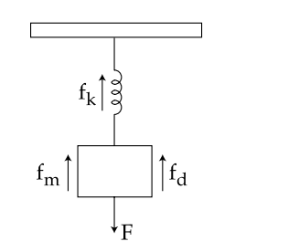
The mass-spring-damper system shown in the following figure represents :
The error detector element in a control system gives
Important Questions from Basics of Control Systems
The term control system means:
Poles are the complex frequencies of a transfer function where the response becomes
Which of the following is the analogous pair under force current analogy?
The electrical capacitance is analog of _________
- Which statement is correct for open loop system?



