
The power dissipation in the resistor R4 of the following circuit will be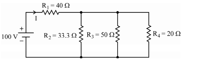
20 watts
Read the topology first. R1 is in series with the source, and R2, R3, R4 all hang between the same two nodes, so they are in parallel. Find the voltage across that parallel group and the rest follows.
Step 1 — combine the parallel resistors.
\(\dfrac{1}{R_p}=\dfrac{1}{33.3}+\dfrac{1}{50}+\dfrac{1}{20}=0.0300+0.0200+0.0500=0.1000\)
\(R_p=10\ \Omega\)
(The numbers are chosen to make this exact: 33.3 Ω contributes 0.03 S, so the three conductances add to a round 0.1 S.)
Step 2 — total resistance and source current.
\(R_T=R_1+R_p=40+10=50\ \Omega\)
\(I=\dfrac{100}{50}=2\ \text{A}\)
Step 3 — voltage across the parallel section. This is the voltage that appears across R4:
\(V_p=I\,R_p=2\times10=20\ \text{V}\)
(Equivalently, the 40 Ω drops 80 V, leaving 20 V of the 100 V supply.)
Step 4 — power in R4.
\(P_4=\dfrac{V_p^{2}}{R_4}=\dfrac{20^{2}}{20}=\dfrac{400}{20}\)
\(P_4=20\ \text{W}\)
Cross-check by current division. The current in R4 is \(20/20=1\ \text{A}\), so \(P_4=I^{2}R_4=1^{2}\times20=20\ \text{W}\) ✓. As a further check, the three branch currents 0.6 A, 0.4 A and 1 A sum to the 2 A supplied ✓.
Where the distractors come from. 100 W is the total power drawn from the source (\(100\times2=200\) W, halved if you slip on the current); 10 W would follow from wrongly taking 10 V across the group, and 15 W from using the wrong branch.
Hence, the power dissipated in R4 is 20 watts.
Similar Questions
Power absorbed by an element for t = 10 sec, if the current magnitude is 2e-0.1t and the voltage across the element is \(V=6\frac{di}{dt}\), the absorbed power is :
A. - 0.325 Watts
B. - 2.4 e-0.2(10) Watts
C. 0.325 Watts
D. 2.4 e-0.2(10) Watts
E. 0.625 Watts
choose the correct answer from the options given below :
Match List I with List II
LIST I LIST II A. Power I. dBi B. Gain II. Watts C. Resistance III. Henry D. Inductance IV. Ohm Choose the correct answer from the options given below:
Consider a star network as shown in the following figure :
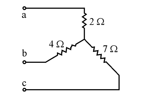
If the resistance between terminals b and c with a open is represented by RA, the resistance between c and a with b open is RB and the resistance between a and b with c open is RC, then arrange RA, RB and RC in descending order.
Important Questions from Network Elements
The maximum safe working voltage for a series combination of two capacitors of rating 2 μF/10V and 4 μF/20V is
Seema has two bulbs, one of them is faulty. She connects both the bulbs in parallel land, not in series. Which of the following is NOT the correct reason to do this?
- The capacitance 'C' is a measure of the capacitor's potential to store energy in:
Capacitor having lowest capacitance has medium of dielectric :
The inductor is a two-terminal energy storage device whose voltage is proportional to the:



