
In the circuit shown below, the voltage appearing across the diode D will be of the form :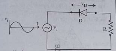
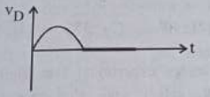
To determine the form of the voltage appearing across the diode \( D \) in the given circuit, let's analyze the circuit operation:
Circuit Overview:
- The circuit consists of an AC voltage source \( V_i \), a diode \( D \), and a resistor \( R \).
Operation of the Diode:
- Diodes allow current to pass through them only in one direction: forward biased and block the current in reverse bias.
- During the positive half-cycle of \( V_i \), the diode becomes forward-biased, and it conducts, allowing the voltage across \( R \) and essentially shorting the diode to a very low forward voltage drop.
- During the negative half-cycle of \( V_i \), the diode is reverse-biased, and it does not conduct, resulting in the voltage across the diode equal to the negative of the input voltage.
Voltage Across the Diode \( V_D \):
- When the diode is forward-biased, \( V_D \) is approximately 0 (or the forward voltage drop, typically about 0.7 V for silicon diodes, but can be assumed negligible for ideal cases).
- When the diode is reverse-biased, \( V_D \) equals \( -V_i \).
Conclusion:
The voltage appearing across the diode \( D \) will therefore have a waveform similar to the negative half of the input voltage waveform when the diode is non-conducting and be near zero during the positive cycle when conducting.
Hence, the correct answer is the waveform option that represents a negative clipping of the input voltage.
Similar Questions
A 100-turn closely wound circular coil of radius $10 \text{ cm}$ has a magnetic field of $3.14 \times 10^{-3} \text{ T}$ at its centre. The current passing through the coil, and the magnitude of the magnetic moment of this coil are, respectively :
(Take $\mu_0 = 4\pi \times 10^{-7} \text{ T m/A}$)The current $I$ in the circuit shown below is :
(All diodes are ideal and identical.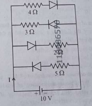
- A galvanometer of resistance $100 \ \Omega$ gives full scale deflection for a current of $1 \text{ mA}$. It is converted into an ammeter of range $0 - 10 \text{ A}$. The shunt required is :
- An ac circuit contains a resistance of $1 \text{ k}\Omega$, a capacitor of $0.1 \ \mu\text{F}$ and an inductor of $1 \text{ mH}$ connected in series. The resonance frequency of the circuit is approximately :
- Consider two uncharged capacitors of equal capacitance $200 \text{ pF}$. One of them is charged by a $100 \text{ V}$ supply and disconnected. Now this capacitor is connected to the uncharged capacitor. The amount of electrostatic energy lost in the process is :
- Two statements are given below :
A. When the forward bias voltage across a p-n junction diode increases above a certain threshold voltage, the diode current increases significantly.
B. This current is called reverse saturation current.
Choose the correct answer from the options given below : - A rectangular wire loop of sides $8 \text{ cm}$ and $3 \text{ cm}$ with a small cut, is moving out of a region of uniform magnetic field of magnitude $0.3 \text{ T}$ directed normal to the plane of the loop. The emf developed across the cut, if the velocity of the loop is $2 \text{ cm s}^{-1}$ in a direction normal to the shorter side of the loop, will be :
- A resistor is connected to a battery of $12 \text{ V}$ emf and internal resistance $2 \ \Omega$. If the current in the circuit is $0.6 \text{ A}$, the terminal voltage of the battery is :
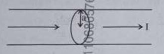
The figure given below shows a long straight solid wire of circular cross-section of radius 'a' carrying steady current I. The current I is uniformly distributed across its cross-section. The plot which correctly represents the variation of magnetic field (B) with distance (r) from the axis of the conductor in the region is :
Five capacitors of capacitances $C_1 = C_2 = C_3 = C_4 = 10 \ \mu\text{F}$ and $C_5 = 2.5 \ \mu\text{F}$ are connected as shown along with a battery of $50 \text{ V}$.
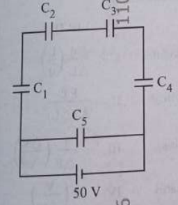
The equivalent capacitance and the charges on each capacitor respectively are :
Important Questions from Electricity and Magnetism
- The electric current in the circuit is given as $i = i_o(t/T)$. The r.m.s current for the period $t = 0$ to $t = T$ is ________.
- In the potentiometer, when the cell in the secondary circuit is shunted with $4\text{ }\Omega$ resistance, the balance is obtained at the length $120\text{ cm}$ of wire. Now when the same cell is shunted with $12\text{ }\Omega$ resistance, the balance is shifted to a length of $180\text{ cm}$. The internal resistance of cell is ________$\Omega$
- The electric field of an electromagnetic wave travelling through a medium is given by $\vec{E}(x,t) = 25 \sin(2.0 \times 10^{15} t - 10^7 x) \hat{n}$
then the refractive index of the medium is ________.
(All given measurement are in SI units) Three long straight wires carrying current are arranged mutually parallel as shown in the figure. The force experienced by $15 \text{ cm}$ length of wire $Q$ is________.
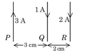
$(\mu_o = 4\pi \times 10^{-7} \text{ T.m/A})$- For the two cells having same EMF $E$ and internal resistance $r$, the current passing through the external resistor $6\text{ }\Omega$ is same when both the cells are connected either in parallel or in series. The value of internal resistance $r$ is ________$\Omega$.


