IC LM 380 is a
Power audio amplifier
The LM380 is a fixed-gain audio power amplifier — option 3. It delivers about 2.5 W into 8 Ω from a single supply of 12 to 22 V, with an internally set voltage gain of 50 (34 dB) and an output that self-centres at half the supply so that no coupling capacitor is needed at its input side.
| Parameter | Value |
|---|---|
| Output power | 2.5 W into 8 Ω |
| Voltage gain | 50, fixed internally |
| Supply | Single, 12 – 22 V |
| Output quiescent level | VCC/2, set internally |
| Package | 14-pin DIP with heat-sink pins |
Why the gain is fixed at 50. The internal feedback network is on-chip, which removes the external components a discrete design would need and guarantees stability — at the cost of flexibility. Its middle pins are bonded to the die's substrate so that the printed-circuit copper acts as the heat sink, which is what allows a plastic DIP to dissipate several watts.
Why the other options are wrong — and what those part numbers would be.
| Function | Typical IC |
|---|---|
| Voltage regulator | LM78xx series, LM317 |
| Rectifier | Not an IC function — discrete diodes or a bridge |
| Audio power amplifier | LM380, LM386, TDA2003 |
| Comparator / Schmitt trigger | LM311, LM339, 74LS14 |
The number is easy to confuse with the LM386, its smaller cousin: 8-pin, 0.5 W, gain 20 by default but settable to 200 by bridging pins 1 and 8 with a capacitor. Both are the standard "one-chip loudspeaker driver" of hobby and instrument electronics.
The classification worth carrying away is that of the four options only two describe things an integrated circuit does at all — regulation and amplification — and the "LM" prefix with a three-digit number in the 300s belongs to National Semiconductor's linear range, of which the LM380 is the audio member.
Hence, the LM380 is a power audio amplifier.
Similar Questions
Consider the following ICs :
1. LM 78 05
2. LM 78 15
3. LM 78 12The correct sequence of the output noise voltage (at 25 °C and for an operating frequency range of 10 Hz ≤ f ≤ 100 KHz) in decreasing order is given by
Assertion (A) : The series pass transistor in a regulator is in class A mode.
Reason (R) : Class A is a switching mode and yields high efficiency.
Important Questions from Power Amplifiers and 555 Timer and Voltage Regulators
Consider the following ICs :
1. LM 78 05
2. LM 78 15
3. LM 78 12The correct sequence of the output noise voltage (at 25 °C and for an operating frequency range of 10 Hz ≤ f ≤ 100 KHz) in decreasing order is given by
Assertion (A) : The series pass transistor in a regulator is in class A mode.
Reason (R) : Class A is a switching mode and yields high efficiency.
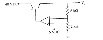
The value of $V_o$ of the series regulator shown below is
In VCO IC 566, the value of charging & discharging is dependent on the voltage applied at ________.
Which among the following are the features of push-pull amplifier?
(i) Noise rejection
(ii) Can give efficiency of more than 50
(iii) Output may have cross over distortion
(iv) Output may have harmonic distortion