
For a two transistor model, the value of α1 + α2 is equal to :
= 1
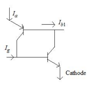
The two-transistor model describes a thyristor, and the condition that marks the boundary of latching is α1 + α2 = 1 — option 3.
The model. A four-layer pnpn structure is split into an interleaved pnp and npn pair, each transistor's collector feeding the other's base. Writing the anode current in terms of both alphas and the leakage gives
\(I_{A}=\dfrac{\alpha_{2}I_{G}+I_{CBO1}+I_{CBO2}}{1-\left(\alpha_{1}+\alpha_{2}\right)}\)
Everything follows from the denominator. As \(\alpha_{1}+\alpha_{2}\) approaches 1 the denominator approaches zero and the anode current rises without bound — that is, it becomes limited only by the external circuit, which is exactly what "turning on" means. So
\(\alpha_{1}+\alpha_{2}=1\)
is the trigger condition, the precise threshold at which regeneration takes over.
| α1 + α2 | Denominator | State |
|---|---|---|
| < 1 | Positive, finite | Forward blocking — only leakage flows |
| = 1 | Zero | Breakover — the device latches |
| > 1 | Would be negative | Not physically sustained — see below |
Why option 1 is a trap worth examining. The regenerative loop needs a loop gain of at least 1 to start, so one might argue for \(\gt1\). But the sum cannot stay above 1: once conduction begins, the large current drives both transistors into saturation, where the alphas fall back and the sum settles at exactly unity. The equality is both the trigger condition and the steady conducting condition, which is why it is the answer.
Why the alphas rise in the first place. Current gain in a bipolar transistor is small at very low currents, because recombination in the emitter-base depletion region takes a large share of the current. As current increases, that share falls and \(\alpha\) climbs towards its full value. This is the mechanism behind every way of firing a thyristor:
Gate current raises \(I_{G}\) and hence the npn section's current directly.
Break-over voltage multiplies the leakage by avalanche.
High dv/dt injects displacement current \(C_{j}\,dv/dt\).
Temperature raises the leakage.
All four do the same thing — push the alphas up until their sum reaches unity.
Why turn-off is hard follows from the same equation: nothing in it involves the gate once conduction has begun, so the anode current must be reduced below the holding value to bring the sum back under 1.
Hence, α1 + α2 = 1.
Similar Questions
In two transistor model of an SCR the expression for anode current is given by:
Which of the following statements are true for SCR ?
(a) UJT is a phase controlling device for SCR rectifier.
(b) The average load voltage of SCR rectifier is greater than average load voltage of ordinary diode rectifier.
(c) Power delivered to the load in SCR rectifier is maximum when SCR firing angle is zero degree.
(d) SCR can control the amount of power fed to the load by switching current OFF and ON upto many thousand times a second.
Match the following lists :
List - I List - II a. SCR can be turned off by i. it turns off when anode current falls below this value. b. Turn on time of SCR can be reduced by ii. the rectangular pulse of high amplitude and narrow width c. Holding current for an SCR means iii. its anode current interruption d. A forward current can be applied to an SCR after iv. its gate recovery time Correct Codes are :
The voltage safety factor (Vf) of a thyristor is given by :
In SCR, the following statements are given :
(a) It acts as a short circuit device.
(b) It acts as an open circuit device.
(c) ON state voltage is approximately 2-5 Volts.
(d) ON state voltage is approximately 50-100 Volts.
Which of the above statements are correct ?
An SCR is turned off by :
Important Questions from Thyristors
_______ exhibit a regenerative switching characteristic.
The minimum anode current, which must flow through the SCR in order for it to stay ON initially after the gate signal is removed, is known as ______.
What is the maximum firing angle achievable using resistance-capacitance triggering of SCR?
Which one of the following can be used in the lighting system for power interruptions?
SCR is



