
The transfer function of the system shown in the following figure is :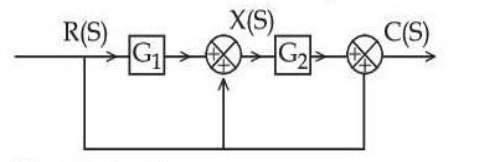
G1G2 + G2 + 1
There is no feedback here — every path runs forward from R to C — so the transfer function is simply the sum of the gains of all the forward paths.
Step 1 — work forward to X(S). The first summing junction receives the output of G1 and a direct connection from R:
\(X(s)=G_{1}R(s)+R(s)=R(s)\left(G_{1}+1\right)\)
Step 2 — through G2 to the second junction. That junction receives \(G_{2}X(s)\) and again a direct connection from R:
\(C(s)=G_{2}X(s)+R(s)=G_{2}R(s)\left(G_{1}+1\right)+R(s)\)
Step 3 — expand and divide.
\(C(s)=R(s)\left[G_{1}G_{2}+G_{2}+1\right]\)
\(\dfrac{C(s)}{R(s)}=G_{1}G_{2}+G_{2}+1\)
— option 4.
Reading it as three parallel paths gives the same answer and makes the structure plain:
| Path from R to C | Gain |
|---|---|
| Through G1 then G2 | G1G2 |
| Direct to the first junction, then through G2 | G2 |
| Direct to the second junction | 1 |
Since the paths are in parallel and no loop exists, the gains simply add — which is Mason's rule with \(\Delta=1\) and every \(\Delta_{k}=1\).
Why option 3 is the trap. It has \(G_{1}\) where the answer needs \(G_{2}\) — that is, it assumes the bypass connection joins after G2 rather than before it. The decisive question is where each direct line enters: the first bypass enters ahead of G2, so it is amplified by G2; the second enters after G2, so it is not amplified at all. Tracing where a signal enters, rather than where it leaves, is what separates the two options.
A check on the result. Setting \(G_{1}=G_{2}=0\) should leave only the direct connection, and the expression correctly gives 1. Setting \(G_{1}=0\) should leave the second path and the direct one, giving \(G_{2}+1\) — which it does. Option 3 fails this second test, since it would give 1.
The absence of any feedback is why no \(1+GH\) denominator appears: with no loop, the characteristic equation is trivial and the system cannot be made unstable by raising the gain.
Hence, C(s)/R(s) = G1G2 + G2 + 1.
Similar Questions
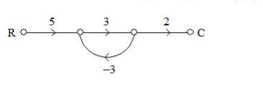
The transfer function of the given signal flow graph is
Match the following lists :
List - I List - II a. 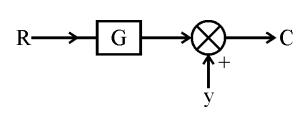
i. 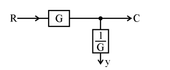
b. 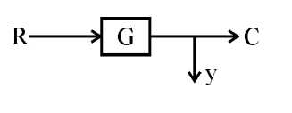
ii. 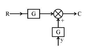
c. 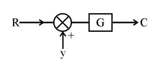
iii. 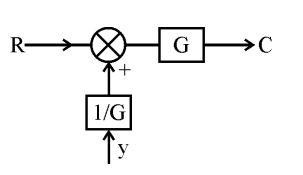
d. 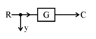
iv. 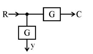
Codes :
Consider the following signal flow graph.
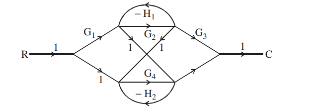
Assume that A is number of forward paths, B is number of feedback loops, C is number of touching loops. Arrange A, B and C in decreasing order :
Important Questions from Block Diagram Reduction Using Signal Flow Graph - Teaching
The transfer function of the given signal flow graph is
Match the following lists :
List - I List - II a. i. b. ii. c. iii. d. iv. Codes :
Consider the following signal flow graph.
Assume that A is number of forward paths, B is number of feedback loops, C is number of touching loops. Arrange A, B and C in decreasing order :



