
Consider the following signal flow graph. Assume that A is number of forward paths, B is number of feedback loops, C is number of touching loops. Arrange A, B and C in decreasing order :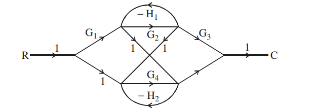
A > B > C
Definitions first. In Mason's terminology a forward path runs from source to sink touching no node more than once; a feedback loop is a closed path returning to its starting node; two loops touch if they share at least one node or branch.
Step 1 — count the forward paths, A. Tracing every route from R to C without repeating a node gives four distinct paths: the upper route through G1 and G2 and then G3; the lower route through G4 and the unity branch; the route that enters through G1 and crosses on the upper diagonal into the lower half; and the route that crosses on the other diagonal from the upper half down into G4. So
\(A=4\)
Step 2 — count the feedback loops, B. The graph has exactly two closed paths, one in each half:
\(L_1=-G_2H_1 \qquad\text{(upper pair)}\)
\(L_2=-G_4H_2 \qquad\text{(lower pair)}\)
No other closed path exists, because the crossing diagonals both run downward — there is no branch carrying a signal back up from the lower half to the upper one, so nothing closes across the two halves. Hence
\(B=2\)
Step 3 — count the touching loops, C. L1 lives entirely on the two upper nodes and L2 entirely on the two lower nodes. They share no node and no branch, so they are non-touching, and the number of touching loops is
\(C=0\)
Step 4 — order them.
\(A=4 \gt B=2 \gt C=0\)
which is option 3.
The check through Mason's formula. Because the two loops are non-touching, the determinant carries their product term:
\(\Delta=1-(L_1+L_2)+L_1L_2=1+G_2H_1+G_4H_2+G_2H_1G_4H_2\)
and the overall gain is \(T=\dfrac{1}{\Delta}\sum_k P_k\Delta_k\). The presence of that \(L_1L_2\) term is itself the confirmation that no loops touch — if they did, the product would be absent and ∆ would reduce to \(1+G_2H_1+G_4H_2\).
Hence, the decreasing order is A > B > C.
Similar Questions
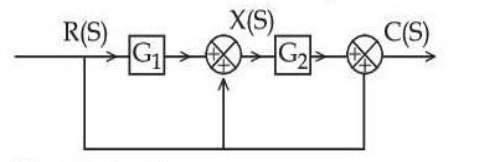
The transfer function of the system shown in the following figure is :
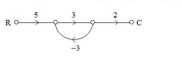
The transfer function of the given signal flow graph is
Match the following lists :
List - I List - II a. 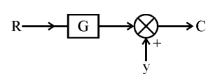
i. 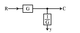
b. 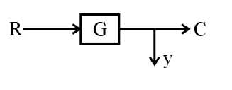
ii. 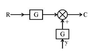
c. 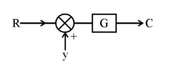
iii. 
d. 
iv. 
Codes :
Important Questions from Block Diagram Reduction Using Signal Flow Graph - Teaching
The transfer function of the system shown in the following figure is :
The transfer function of the given signal flow graph is
Match the following lists :
List - I List - II a. i. b. ii. c. iii. d. iv. Codes :



