List - I
RelationList - II
LawA. $\oint \vec{E} \cdot d\vec{l} = -\frac{d}{dt} \oint \vec{B} \cdot d\vec{a}$ I. Ampere's circuital law B. $\oint \vec{B} \cdot d\vec{l} = \mu_0 \left(I + \epsilon_0 \frac{d\phi_E}{dt}\right)$ II. Faraday's laws of electromagnetic induction C. $\oint \vec{E} \cdot d\vec{a} = \frac{1}{\epsilon_0} \int_v \rho dv$ III. Ampere - Maxwell law D. $\oint \vec{B} \cdot d\vec{l} = \mu_0 I$ IV. Gauss's law of electrostatics
Choose the correct answer from the options given below :
Matching Electromagnetism Laws
This question requires matching the integral forms of physical laws presented in List - I with their corresponding names in List - II.
The correct pairings, corresponding to the provided answer option B, are determined as follows:
- A: The expression $\oint \vec{E} \cdot d\vec{l} = -\frac{d}{dt} \oint \vec{B} \cdot d\vec{a}$ is associated with I. Ampere's circuital law.
- B: The expression $\oint \vec{B} \cdot d\vec{l} = \mu_0 \left(I + \epsilon_0 \frac{d\phi_E}{dt}\right)$ is associated with IV. Gauss's law of electrostatics.
- C: The expression $\oint \vec{E} \cdot d\vec{a} = \frac{1}{\epsilon_0} \int_v \rho dv$ is associated with III. Ampere - Maxwell law.
- D: The expression $\oint \vec{B} \cdot d\vec{l} = \mu_0 I$ is associated with II. Faraday's laws of electromagnetic induction.
This leads to the specific matching: A-I, B-IV, C-III, D-II.
Similar Questions
- Two electrons are moving in orbits of two hydrogen like atoms with speeds $3 \times 10^5 \text{ m/s}$ and $2.5 \times 10^5 \text{ m/s}$ respectively. If the radii of these orbits are nearly same then the possible order of energy states are ______ respectively.
- Given below are two statements:
Statement I: For all elements, greater the mass of the nucleus, greater is the binding energy per nucleon.
Statement II: For all elements, nuclei with less binding energy per nucleon transforms to nuclei with greater binding energy per nucleon.
In the light of the above statements, choose the correct answer from the options given below - A voltage regulating circuit consisting of Zener diode, having break-down voltage of 10 V and maximum power dissipation of 0.4 W, is operated at 15 V. The approximate value of protective resistance in this circuit is ______ $\Omega$.
The binding energy for the following nuclear reactions are expressed in MeV.
${}_2\text{He}^3 + {}_0\text{n}^1 \rightarrow {}_2\text{He}^4 + 20 \text{ MeV}$
${}_2\text{He}^4 + {}_0\text{n}^1 \rightarrow {}_2\text{He}^5 - 0.9 \text{ MeV}$
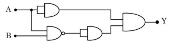
If $\text{X}_3, \text{X}_4, \text{X}_5$ denote the stability of ${}_2\text{He}^3, {}_2\text{He}^4$ and ${}_2\text{He}^5$, respectively, then the correct order is :Identify the correct truth table of the given logic circuit.
- When a light of a given wavelength falls on a metallic surface the stopping potential for photoelectrons is $3.2 \text{ V}$. If a second light having wavelength twice of first light is used, the stopping potential drops to $0.7 \text{ V}$. The wavelength of first light is _______ m.
($h = 6.63 \times 10^{-34} \text{ J.s}, e = 1.6 \times 10^{-19} \text{ C}, c = 3 \times 10^8 \text{ m/s}$) - A particle having electric charge $3 \times 10^{-19}\text{ C}$ and mass $6 \times 10^{-27}\text{ kg}$ is accelerated by applying an electric potential of $1.21\text{ V}$. Wavelength of the matter wave associated with the particle is $\alpha \times 10^{-12}\text{ m}$. The value of $\alpha$ is __________. (Take Planck's constant $= 6.6 \times 10^{-34}\text{ J.s}$)
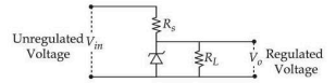
The following diagram shows a Zener diode as a voltage regulator. The Zener diode is rated at $V_z = 5\text{ V}$ and the desired current in load is 5 mA. The unregulated voltage source can supply upto 25 V. Considering the Zener diode can withstand four times of the load current, the value of resistor $R_s$ (shown in circuit) should be ___________ $\Omega$.
- In hydrogen atom spectrum, ($R \to$ Rydberg's constant)
A. the maximum wavelength of the radiation of Lyman series is $\frac{4}{3R}$
B. the Balmer series lies in the visible region of the spectrum
C. the minimum wavelength of the radiation of Paschen series is $\frac{9}{R}$
D. the minimum wavelength of Lyman series is $\frac{5}{4R}$
Choose the correct answer from the options given below : - The de Broglie wavelength of an oxygen molecule at $27^\circ\text{C}$ is $x \times 10^{-12}\text{ m}$. The value of $x$ is (take Planck's constant $= 6.63 \times 10^{-34}\text{ J.s}$, Boltzmann constant $= 1.38 \times 10^{-23}\text{ J/K}$, mass of oxygen molecule $= 5.31 \times 10^{-26}\text{ kg}$)
Important Questions from Modern Physics
- Two electrons are moving in orbits of two hydrogen like atoms with speeds $3 \times 10^5 \text{ m/s}$ and $2.5 \times 10^5 \text{ m/s}$ respectively. If the radii of these orbits are nearly same then the possible order of energy states are ______ respectively.
- Given below are two statements:
Statement I: For all elements, greater the mass of the nucleus, greater is the binding energy per nucleon.
Statement II: For all elements, nuclei with less binding energy per nucleon transforms to nuclei with greater binding energy per nucleon.
In the light of the above statements, choose the correct answer from the options given below - A voltage regulating circuit consisting of Zener diode, having break-down voltage of 10 V and maximum power dissipation of 0.4 W, is operated at 15 V. The approximate value of protective resistance in this circuit is ______ $\Omega$.
The binding energy for the following nuclear reactions are expressed in MeV.
${}_2\text{He}^3 + {}_0\text{n}^1 \rightarrow {}_2\text{He}^4 + 20 \text{ MeV}$
${}_2\text{He}^4 + {}_0\text{n}^1 \rightarrow {}_2\text{He}^5 - 0.9 \text{ MeV}$
If $\text{X}_3, \text{X}_4, \text{X}_5$ denote the stability of ${}_2\text{He}^3, {}_2\text{He}^4$ and ${}_2\text{He}^5$, respectively, then the correct order is :Identify the correct truth table of the given logic circuit.