
Choose the correct experimental circuit arrangement for studying V-I characteristics of a p-n junction diode in forward bias:
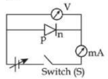
In forward bias, the p-side of the diode is connected to the positive terminal of the power supply, and the n-side is connected to the negative terminal. This reduces the potential barrier, allowing current to flow. The correct experimental setup ensures proper voltage and current measurement using an ammeter and a voltmeter. In option (c), the circuit correctly connects the diode in forward bias with appropriate measuring instruments, making it the correct answer.
Important Questions from Semiconductor and Electronic Devices
If the forward voltage in a p-n junction diode is increased, the width of the depletion region:
Two identical thin metal plates are given charges q1 and q2 (q2 < q1) respectively. If they are now brought close together to form a parallel plate capacitor with a capacitance 'C', then the potential difference between the plates is:
Displacement current (id) = ω0 dΦE / dt. Where symbols have their usual meanings. Which of the following options gives correct equation for displacement current?
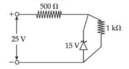
A Zener diode is used in a voltage regulator circuit as shown below. Its breakdown voltage is 15 V. What is the current flowing through the Zener diode?
During the p-n junction formation, when an electron diffuses from n → p, it leaves behind an:


