
Displacement current (id) = ω0 dΦE / dt. Where symbols have their usual meanings. Which of the following options gives correct equation for displacement current?
id = Aω0 dE / dt
Understanding Displacement Current Calculation
The question asks for the correct equation for displacement current (\(i_d\)) based on the given definition: \( i_d = \omega_0 \frac{d\Phi_E}{dt} \). Here, \( \Phi_E \) represents the electric flux, and other symbols have their usual meanings.
Defining Electric Flux (\(\Phi_E\))
Electric flux measures the amount of electric field passing through a given area. Mathematically, the electric flux (\(\Phi_E\)) through a surface is defined by the integral of the electric field (\(\vec{E}\)) dotted with the differential area vector (\(d\vec{A}\)) over the surface:
\( \Phi_E = \int \vec{E} \cdot d\vec{A} \)
For a simple case, such as a uniform electric field (\(\vec{E}\)) perpendicular to a flat surface with area (\(A\)), the electric flux simplifies to:
\( \Phi_E = E \times A \)
where \(E\) is the magnitude of the electric field and \(A\) is the area.
Deriving the Displacement Current Equation
We are given the definition of displacement current as:
\( i_d = \omega_0 \frac{d\Phi_E}{dt} \)
Substitute the simplified expression for electric flux (\( \Phi_E = EA \)) into this equation:
\( i_d = \omega_0 \frac{d(EA)}{dt} \)
In many physical situations, the area \(A\) through which the electric flux is changing remains constant over time (for example, the area between the plates of a charging capacitor). If we assume \(A\) is constant, we can take \(A\) outside the time derivative:
\( i_d = \omega_0 A \frac{dE}{dt} \)
This equation shows that the displacement current is proportional to the rate of change of the electric field through a given area \(A\), scaled by the constant \( \omega_0 \) and the area \(A\).
Comparing with the Options
Let's compare our derived equation \( i_d = \omega_0 A \frac{dE}{dt} \) with the given options:
- Option 1: \( i_d = \omega_0 \frac{d(BA)}{dt} \). This involves the magnetic field \(B\), not the electric field or electric flux change.
- Option 2: \( i_d = A\omega_0 \frac{dE}{dt} \). This matches our derived equation \( i_d = \omega_0 A \frac{dE}{dt} \).
- Option 3: \( i_d = qA\omega_0 \frac{dE}{dt} \). This includes the charge \(q\), which is not present in our derivation based purely on the change in electric flux.
- Option 4: \( i_d = \frac{A\omega_0}{q} \frac{dE}{dt} \). This also includes the charge \(q\), which is not part of our derivation.
Based on the given definition of displacement current \( i_d = \omega_0 \frac{d\Phi_E}{dt} \) and the relationship \( \Phi_E = EA \) for a constant area \(A\) and changing electric field \(E\), the correct expression for displacement current is \( i_d = A\omega_0 \frac{dE}{dt} \).
| Option | Equation | Comparison |
|---|---|---|
| 1 | \( i_d = \omega_0 \frac{d(BA)}{dt} \) | Involves magnetic field \(B\), incorrect. |
| 2 | \( i_d = A\omega_0 \frac{dE}{dt} \) | Matches derived equation \( i_d = \omega_0 A \frac{dE}{dt} \). |
| 3 | \( i_d = qA\omega_0 \frac{dE}{dt} \) | Includes charge \(q\), incorrect. |
| 4 | \( i_d = \frac{A\omega_0}{q} \frac{dE}{dt} \) | Includes charge \(q\), incorrect. |
Displacement Current Formula
The equation for displacement current, based on the definition provided in the question, is directly obtained by substituting the electric flux formula \( \Phi_E = EA \) (assuming constant area) into the given displacement current definition.
Given: \( i_d = \omega_0 \frac{d\Phi_E}{dt} \)
Using \( \Phi_E = EA \), where \(A\) is constant:
\( i_d = \omega_0 \frac{d(EA)}{dt} = \omega_0 A \frac{dE}{dt} \)
Rearranging the terms gives \( i_d = A\omega_0 \frac{dE}{dt} \).
Revision Table: Key Concepts
| Concept | Description / Formula |
|---|---|
| Electric Flux (\(\Phi_E\)) | Flow of electric field through a surface. For uniform \(E\) perpendicular to area \(A\): \( \Phi_E = EA \) |
| Displacement Current (\(i_d\)) | A term introduced by Maxwell representing changing electric flux. Given definition: \( i_d = \omega_0 \frac{d\Phi_E}{dt} \) |
| Relationship to Electric Field Change | For constant area \(A\): \( i_d = \omega_0 A \frac{dE}{dt} \) |
Additional Information: Role of Displacement Current
Displacement current was a crucial concept introduced by James Clerk Maxwell to complete Ampère's circuital law. Ampère's law relates the circulation of the magnetic field to the conduction current. However, it failed in situations where electric fields are changing, such as in a charging capacitor. Maxwell realized that a changing electric flux also produces a magnetic field, just like a conduction current does. He added the displacement current term to Ampère's law, forming one of Maxwell's equations:
\( \oint \vec{B} \cdot d\vec{l} = \mu_0 (I_{conduction} + I_{displacement}) \)
where \( I_{displacement} \) is usually given by \( \epsilon_0 \frac{d\Phi_E}{dt} \). The question uses \( \omega_0 \) instead of \( \epsilon_0 \), which is a variation on the standard formula but the principle remains the same: it accounts for the magnetic field produced by a changing electric field.
The inclusion of displacement current demonstrated the symmetry between electric and magnetic fields and predicted the existence of electromagnetic waves, which propagate through space at the speed of light. These waves consist of mutually sustaining changing electric and magnetic fields.
Understanding displacement current is key to understanding how electromagnetic waves are generated and propagate, and how electric and magnetic fields are interconnected.
Important Questions from Semiconductor and Electronic Devices
Silicon can be doped using one of the following elements as dopant:
(A) Arsenic
(B) Indium
(C) Phosphorus
(D) BoronTo get an n-type semiconductor, the dopants that can be used are:
Let iE, iC, and iB represent the emitter current, collector current, and the base current respectively in a transistor. Choose the correct statement:
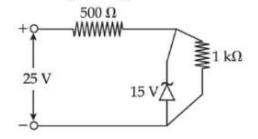
A Zener diode is used in a voltage regulator circuit as shown below. Its breakdown voltage is 15 V. What is the current flowing through the Zener diode?
Choose the correct experimental circuit arrangement for studying V-I characteristics of a p-n junction diode in forward bias:
During the p-n junction formation, when an electron diffuses from n → p, it leaves behind an:


