
Two identical thin metal plates are given charges q1 and q2 (q2 < q1) respectively. If they are now brought close together to form a parallel plate capacitor with a capacitance 'C', then the potential difference between the plates is:
(q1 - q2) / 2C
Calculating Potential Difference in Parallel Plate Capacitors
Let's analyze how the potential difference is determined for two identical thin metal plates given charges \(q_1\) and \(q_2\) that are brought close together to form a parallel plate capacitor with capacitance \(C\).
Charge Distribution on Parallel Plates
When two charged conductive plates are brought near each other, the charges redistribute themselves. For thin plates placed parallel and close to each other, the charge on the inner surfaces will be equal and opposite due to electrostatic induction, while the remaining charge will reside on the outer surfaces.
Let the total charge on plate 1 be \(q_1\) and on plate 2 be \(q_2\).
- Let \(q_{inner1}\) be the charge on the inner surface of plate 1.
- Let \(q_{outer1}\) be the charge on the outer surface of plate 1.
- Let \(q_{inner2}\) be the charge on the inner surface of plate 2.
- Let \(q_{outer2}\) be the charge on the outer surface of plate 2.
The total charge on each plate is the sum of the charges on its inner and outer surfaces:
- \(q_1 = q_{inner1} + q_{outer1}\)
- \(q_2 = q_{inner2} + q_{outer2}\)
For parallel plates, the charges on the inner surfaces are equal in magnitude and opposite in sign:
- \(q_{inner1} = -q_{inner2}\). Let's call this charge \(Q_{inner}\).
- So, \(q_{inner1} = Q_{inner}\) and \(q_{inner2} = -Q_{inner}\).
The total charge of the system (\(q_1 + q_2\)) is shared equally between the two outer surfaces when the plates are close together and far from other conductors:
- \(q_{outer1} = q_{outer2} = \frac{q_1 + q_2}{2}\)
Finding the Charge on Inner Surfaces (\(Q_{inner}\))
Now we can express the total charges \(q_1\) and \(q_2\) in terms of \(Q_{inner}\) and the outer charges:
- \(q_1 = Q_{inner} + \frac{q_1 + q_2}{2}\)
- \(q_2 = -Q_{inner} + \frac{q_1 + q_2}{2}\)
We can solve for \(Q_{inner}\) from either equation. Using the first equation:
\(Q_{inner} = q_1 - \frac{q_1 + q_2}{2}\)
\(Q_{inner} = \frac{2q_1 - (q_1 + q_2)}{2}\)
\(Q_{inner} = \frac{2q_1 - q_1 - q_2}{2}\)
\(Q_{inner} = \frac{q_1 - q_2}{2}\)
The charge of the capacitor is the magnitude of the charge on one of the inner surfaces, which is \(|Q_{inner}|\).
Given that \(q_2 < q_1\), the term \((q_1 - q_2)\) is positive. Therefore, \(|Q_{inner}| = \frac{q_1 - q_2}{2}\).
Calculating the Potential Difference
The potential difference (\(V\)) across a capacitor is related to the charge (\(Q\)) stored on it and its capacitance (\(C\)) by the formula:
\(V = \frac{Q}{C}\)
In this case, the effective charge \(Q\) contributing to the potential difference is the charge on the inner surfaces, \(|Q_{inner}|\).
So, the potential difference \(V\) between the plates is:
\(V = \frac{|Q_{inner}|}{C}\)
\(V = \frac{\frac{q_1 - q_2}{2}}{C}\)
\(V = \frac{q_1 - q_2}{2C}\)
This calculation aligns with one of the provided options.
Revision Table: Parallel Plate Capacitors
| Concept | Description |
|---|---|
| Parallel Plate Capacitor | Consists of two conductive plates separated by a dielectric medium (or vacuum). |
| Capacitance (C) | A measure of a capacitor's ability to store electric charge. Defined as \(C = Q/V\), where Q is the charge stored and V is the potential difference. |
| Charge Distribution (Parallel Plates) | Total charge Q1 and Q2 on plates results in inner charges \( \pm (Q_1 - Q_2)/2 \) and outer charges \( (Q_1 + Q_2)/2 \) each. |
| Potential Difference (V) | The work done per unit charge to move a charge between the plates. Calculated as \(V = Q_{inner} / C\). |
Additional Information: Capacitor Concepts
Understanding how charge distributes on conductors is crucial for solving problems involving capacitors. In a parallel plate capacitor, the electric field between the plates is primarily due to the charges on the inner surfaces. The charges on the outer surfaces tend to distribute themselves evenly across the external surface area and do not contribute significantly to the field *between* the plates, especially when the plates are large and close together compared to their separation.
The potential difference is directly proportional to the charge stored and inversely proportional to the capacitance. The capacitance \(C\) depends on the geometry of the plates (area \(A\) and separation \(d\)) and the dielectric material between them (permittivity \(\epsilon\)): \(C = \frac{\epsilon A}{d}\) for a vacuum or air, \(\epsilon\) is \(\epsilon_0\)).
The question provides the capacitance \(C\) directly, so we don't need to calculate it from geometry. The key is to correctly identify the effective charge that contributes to the potential difference between the plates, which is the charge accumulated on the inner surfaces due to the initial charges \(q_1\) and \(q_2\).
Important Questions from Semiconductor and Electronic Devices
Silicon can be doped using one of the following elements as dopant:
(A) Arsenic
(B) Indium
(C) Phosphorus
(D) BoronTo get an n-type semiconductor, the dopants that can be used are:
Let iE, iC, and iB represent the emitter current, collector current, and the base current respectively in a transistor. Choose the correct statement:
A Zener diode is used in a voltage regulator circuit as shown below. Its breakdown voltage is 15 V. What is the current flowing through the Zener diode?
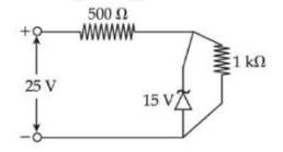
Choose the correct experimental circuit arrangement for studying V-I characteristics of a p-n junction diode in forward bias:
During the p-n junction formation, when an electron diffuses from n → p, it leaves behind an:


