
A p-n junction diode can be used:
To convert AC voltage into DC voltage
Understanding the P-N Junction Diode Function
A p-n junction diode is a fundamental semiconductor device with unique electrical properties. It is created by joining a p-type semiconductor material (with excess holes) and an n-type semiconductor material (with excess electrons).
The key characteristic of a p-n junction diode is its ability to allow current to flow primarily in one direction while significantly resisting current flow in the opposite direction. This property is called rectification.
How a P-N Junction Diode Behaves
- Forward Bias: When the positive terminal of a voltage source is connected to the p-type side and the negative terminal to the n-type side, the diode is forward-biased. This reduces the potential barrier across the junction, allowing a large current to flow through the diode.
- Reverse Bias: When the positive terminal of the voltage source is connected to the n-type side and the negative terminal to the p-type side, the diode is reverse-biased. This increases the potential barrier, allowing only a very small leakage current to flow (ideally zero).
P-N Junction Diode for Voltage Conversion
Based on its unidirectional conductivity, a p-n junction diode is commonly used in electronic circuits, particularly for converting alternating current (AC) voltage into direct current (DC) voltage. This process is known as rectification.
Let's look at why a p-n junction diode is used for this purpose and analyze the given options:
- AC Voltage: AC voltage constantly changes its polarity over time, alternating between positive and negative values.
- DC Voltage: DC voltage maintains a constant polarity, flowing in essentially one direction.
When an AC voltage is applied across a p-n junction diode, the diode becomes forward-biased during one half-cycle (when the voltage polarity matches the forward bias configuration) and reverse-biased during the other half-cycle (when the voltage polarity matches the reverse bias configuration).
During the forward-biased half-cycle, the diode allows current to pass, creating a voltage drop across a connected load. During the reverse-biased half-cycle, the diode blocks significant current flow. The output voltage across the load therefore consists mainly of the positive (or negative, depending on diode orientation) halves of the AC input, effectively converting the alternating voltage into a pulsating DC voltage.
Analyzing the Options
Let's examine the provided options based on the properties of a p-n junction diode:
- To convert DC voltage into AC voltage: This is incorrect. Converting DC to AC is the function of an inverter, not a p-n junction diode. A diode rectifies AC to DC.
- To convert AC voltage into DC voltage: This is correct. As explained above, the unidirectional conductivity of the p-n junction diode allows it to block the reverse-biased portion of an AC waveform, resulting in a pulsating DC output.
- To decrease the amplitude of AC voltage: While a diode circuit might have voltage drops, its primary function isn't amplitude reduction. Devices like transformers are used for changing AC voltage amplitude.
- To decrease the frequency of AC voltage: This is incorrect. A p-n junction diode doesn't directly change the frequency of the AC voltage. The output waveform is derived from the input frequency.
Therefore, the most common and fundamental application of a p-n junction diode is in converting AC voltage into DC voltage through the process of rectification.
| Electronic Component | Primary Function |
|---|---|
| P-N Junction Diode | Rectification (AC to DC conversion) |
| Inverter | DC to AC conversion |
| Transformer | Changing AC voltage amplitude (step-up/step-down) |
| Filter Circuits (e.g., capacitors, inductors) | Smoothing pulsating DC, frequency filtering |
Revision Table: P-N Junction Diode Applications
| Bias Condition | Current Flow | Application Principle |
|---|---|---|
| Forward Bias | Allows significant current | Used as a switch (ON state), part of rectifier circuits |
| Reverse Bias | Blocks significant current (except small leakage) | Used as a switch (OFF state), breakdown region in Zener diodes for voltage regulation |
Additional Information: Rectification Types
Rectification using p-n junction diodes can be implemented in different circuit configurations:
- Half-Wave Rectifier: Uses one diode. It allows only one half-cycle of the AC input to pass, blocking the other half. The output is a pulsating DC.
- Full-Wave Rectifier: Uses multiple diodes (two in a center-tapped configuration or four in a bridge configuration). It utilizes both halves of the AC input cycle to produce a more continuous (though still pulsating) DC output. This results in a higher average DC voltage and is easier to filter into smooth DC.
The pulsating DC output from a rectifier circuit is often passed through a filter circuit (typically using capacitors) to smooth out the variations and produce a more stable DC voltage, which is then often regulated further if a precise voltage is needed.
Important Questions from Semiconductor and Electronic Devices
If the forward voltage in a p-n junction diode is increased, the width of the depletion region:
Two identical thin metal plates are given charges q1 and q2 (q2 < q1) respectively. If they are now brought close together to form a parallel plate capacitor with a capacitance 'C', then the potential difference between the plates is:
Displacement current (id) = ω0 dΦE / dt. Where symbols have their usual meanings. Which of the following options gives correct equation for displacement current?
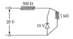
A Zener diode is used in a voltage regulator circuit as shown below. Its breakdown voltage is 15 V. What is the current flowing through the Zener diode?
Choose the correct experimental circuit arrangement for studying V-I characteristics of a p-n junction diode in forward bias:


