
Which of the following circuit is used to obtain pulse gate triggering?
UJT based relaxation oscillator circuit
In power electronics, triggering circuits play a crucial role in controlling the turn-on of semiconductor devices like Thyristors, commonly known as SCRs (Silicon Controlled Rectifiers). The question asks about the specific circuit used to obtain pulse gate triggering.
Pulse Gate Triggering Explained
Pulse gate triggering involves applying short, sharp voltage or current pulses to the gate terminal of a thyristor. This method is preferred over continuous gate current for several reasons:
- It reduces power dissipation in the gate circuit, leading to less heat generation.
- It helps prevent accidental turn-on of the thyristor due to electrical noise or spurious signals.
- It provides a high initial gate current, which ensures rapid and reliable turn-on of the thyristor, especially important for controlling inductive loads.
UJT Based Relaxation Oscillator Circuit
The UJT based relaxation oscillator circuit is widely recognized as the most effective and commonly used method for generating sharp, repetitive gate pulses for triggering SCRs. UJT stands for Unijunction Transistor, a three-terminal semiconductor device that exhibits a unique negative resistance characteristic, making it an excellent component for oscillator and timing applications.
Working Principle of UJT Relaxation Oscillator:
| Component | Role in Circuit |
|---|---|
| Resistor (\(R\)) | Controls the charging current for the capacitor. By changing its value, the charging time and thus the frequency of the pulses can be adjusted. |
| Capacitor (\(C\)) | Charges through the resistor \(R\). Once its voltage reaches a specific threshold, it rapidly discharges through the UJT, creating a pulse. |
| Unijunction Transistor (UJT) | Acts as a voltage-controlled switch. When the voltage across the capacitor (\(V_C\)) reaches the UJT's peak point voltage (\(V_P\)), the UJT's emitter-base1 junction becomes forward-biased and turns ON. This provides a very low resistance path for the capacitor to discharge. The rapid discharge current flows through a small resistor connected to base B1, generating a sharp voltage pulse across it. Once the capacitor discharges to the UJT's valley point voltage (\(V_V\)), the UJT turns OFF, and the cycle repeats. |
The sharp voltage pulse generated across the output resistor (typically connected to base B1) is then directly applied to the gate terminal of the thyristor. This pulse provides the necessary gate current to switch the thyristor into its conducting state. The UJT relaxation oscillator offers a stable frequency of oscillation and is relatively simple to construct, making it a popular choice for precise thyristor triggering.
Other Triggering Circuits Analysis
Let's briefly examine why other options are typically not used for precise pulse gate triggering, or serve different primary purposes:
- Resistive triggering circuit: This is a very basic and simple circuit. It provides a continuous gate current to the SCR when the anode-cathode voltage is positive and the gate resistor allows sufficient current. It does not generate distinct pulses and offers very limited control over the firing angle. It's suitable only for applications where the SCR needs to be turned ON at the very beginning of the positive half-cycle, without any phase control.
- Resistance-capacitance (RC) triggering circuit: RC triggering circuits are commonly used for phase control of SCRs. They provide a variable phase-shifted voltage to the gate, allowing the firing angle to be adjusted. However, while they can initiate turn-on, they generally do not produce the sharp, high-amplitude, and narrow pulses that an UJT relaxation oscillator does, which are crucial for reliable and rapid turn-on, especially with large SCRs or inductive loads. The gate signal from an RC circuit is often more ramp-like or sinusoidal, depending on the configuration.
- Diac-Triac circuit: This circuit is primarily designed for controlling AC power, typically by triggering a TRIAC (Triode for Alternating Current). A DIAC (Diode for Alternating Current) is a bidirectional trigger device that turns on and conducts when its break-over voltage is reached in either direction, providing a pulse to trigger the TRIAC. While it generates pulses, its primary application is in AC phase control with TRIACs for dimmers, fan speed controllers, etc., rather than as a general-purpose, variable-frequency pulse generator for SCRs like a UJT oscillator.
Therefore, for effective and reliable pulse gate triggering of Thyristors, the UJT based relaxation oscillator circuit is the most suitable and commonly employed option due to its ability to generate sharp, consistent pulses.
Important Questions from Power Semiconductor Diodes and Transistors
Which semiconductor power device, out of the following, is not a current triggered device?
A charger supplies 100 W at 20 V for charging the battery of a laptop. The power devices, used in the converter inside the charger, operate at a switching frequency of 200 kHz. Which power device is best suited for this purpose?
Diacs are primarily used as:
The figure shows a straight-line approximation for the forward characteristics of a power diode. A continuous on-state current of 15 A is flowing through the diode.
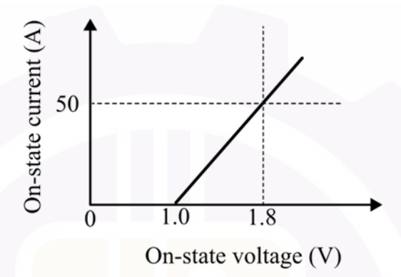
What is the power loss in the diode?
For a system with $G(S)=\frac{k}{S(S+1)(S+2)}$, $H(S)=1$. Determine the brake away point.


