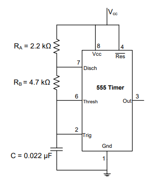
What is the time period of a monostable 555 multivibrator?
T = 1.1RC
Understanding the Monostable 555 Timer Time Period
A monostable multivibrator, often called a one-shot pulse generator, is a circuit that produces a single pulse of a specific duration when triggered. The popular 555 timer IC is commonly used to build monostable circuits.
In a monostable 555 timer circuit, the duration of the output pulse (the time period T) is determined by the values of an external resistor (R) and an external capacitor (C). These components are connected to form an RC timing network.
When the 555 timer is triggered, the capacitor C begins to charge through the resistor R. The output pulse remains high until the voltage across the capacitor reaches two-thirds (2/3) of the supply voltage (VCC). At this point, the internal comparator of the 555 timer resets the flip-flop, discharging the capacitor and returning the output to its low state.
The time it takes for the capacitor to charge from near 0V to (2/3)VCC is the duration of the output pulse, which is the time period (T) of the monostable circuit.
Calculating the Monostable 555 Timer Time Period
The standard formula derived from the capacitor charging equation for the time period (T) of a monostable 555 timer is:
\begin{equation*} T = 1.1 \times R \times C \end{equation*}
Where:
- T is the time period of the output pulse (in seconds)
- R is the value of the external resistor (in ohms)
- C is the value of the external capacitor (in farads)
- The factor 1.1 is approximately $\ln(3)$.
This formula shows that the pulse duration is directly proportional to the values of both the timing resistor R and the timing capacitor C.
Analyzing the Options
Let's compare the derived formula for the monostable 555 timer time period with the given options:
- Option 1: T = 3RC
- Option 2: T = RC
- Option 3: T = 1.1RC
- Option 4: T = 0.33RC
Comparing these options with the standard formula $T = 1.1 RC$, we see that Option 3 matches the correct formula for the time period of a monostable 555 multivibrator.
Conclusion on Monostable 555 Timer Time Period
The time period of a monostable 555 multivibrator is determined by the external timing resistor (R) and capacitor (C) and is given by the formula $T = 1.1 RC$.
Revision Table: Monostable 555 Timer
| Aspect | Description |
|---|---|
| Mode of Operation | Monostable (One-shot) |
| Output Type | Single pulse of fixed duration |
| Trigger | Requires an external trigger pulse |
| Timing Components | External Resistor (R) and Capacitor (C) |
| Time Period (Pulse Width) Formula | $T = 1.1 RC$ |
Additional Information: 555 Timer Modes
The 555 timer IC is a versatile component that can operate in different modes. The monostable mode is just one of them. The other common mode is the astable mode.
- Monostable Mode: Produces a single output pulse when triggered. The pulse duration is set by R and C.
- Astable Mode: Operates as a free-running oscillator, continuously producing a square wave output. In this mode, two resistors and one capacitor are typically used. The frequency and duty cycle of the square wave are determined by the values of these components.
Understanding both monostable and astable operations of the 555 timer is crucial for designing various timing and oscillation circuits.
Important Questions from 555 Timer
In 555 astable multivibrator, R a= 22 k, R b= 39 K and C = 0.01 μf. Calculate the width of the positive pulse.
The control terminal (pin5) of 555 timer IC is normally connected to ground through a capacitor (∼ 0.01μF). This is to
What is the most popular IC used in timing circuits?
The 555 timer IC can have operating modes as:
In the astable multivibrator circuit shown in the figure, the frequency of oscillation (in kHz) at the output pin 3 is _____________