For a tightly wound coil of wire, composed of N identical turns, each with the same ΦB, ________ of induction states that \(\varepsilon=-\dfrac{d\Phi_B}{dt}\) where N is the number of turns of wire and ΦB is the magnetic flux through a single loop.
Faraday’s law
The question asks to identify the fundamental law of induction that governs the relationship between the induced electromotive force (\(\varepsilon\)) and the rate of change of magnetic flux (\(\Phi_B\)) through a tightly wound coil of N identical turns, as represented by the formula \(\varepsilon=-\dfrac{d\Phi_B}{dt}\).
Faraday’s Law of Electromagnetic Induction Explained
Faraday’s law of electromagnetic induction is a cornerstone principle in electromagnetism. It describes how a changing magnetic field can induce an electric current (and thus an electromotive force or EMF) in a conductor. This phenomenon is broadly known as electromagnetic induction.
The essence of Faraday's law states that the magnitude of the induced electromotive force in a circuit is directly proportional to the rate at which the magnetic flux (\(\Phi_B\)) through the circuit changes over time. Mathematically, for a single loop of wire, the induced EMF is precisely given by:
\[ \varepsilon = -\frac{d\Phi_B}{dt} \]
Where:
- \(\varepsilon\) represents the induced electromotive force (EMF), measured in volts (V).
- \(\Phi_B\) is the magnetic flux, measured in webers (Wb). It quantifies the total number of magnetic field lines passing through a given area.
- \(\frac{d\Phi_B}{dt}\) denotes the rate of change of magnetic flux with respect to time, measured in webers per second (Wb/s).
The negative sign in the formula is crucial and is explained by Lenz's Law. Lenz's Law specifies that the direction of the induced current and the induced EMF will always oppose the change in magnetic flux that caused it. This opposition ensures the conservation of energy.
Coil Turns and Magnetic Flux Induction
When dealing with a tightly wound coil composed of N identical turns, as mentioned in the question, the total induced electromotive force (\(\varepsilon_{total}\)) across the entire coil is the sum of the EMFs induced in each individual turn. Assuming the same magnetic flux \(\Phi_B\) passes through each turn, the total induced EMF for the coil is given by:
\[ \varepsilon_{total} = -N \frac{d\Phi_B}{dt} \]
The formula provided in the question, \(\varepsilon=-\dfrac{d\Phi_B}{dt}\), is the foundational part of Faraday's law and specifically represents the induced EMF for a single loop, or alternatively, the EMF induced per turn in a multi-turn coil. Despite the mention of 'N identical turns' and the formula appearing without 'N', the core principle linking the rate of change of magnetic flux to induced electromotive force remains unequivocally that of Faraday's law of induction.
Examining Other Electrical Laws
To further understand why Faraday's law is the correct choice, let's briefly consider the other options provided:
| Law/Theorem | Primary Application and Description | Relevance to Electromagnetic Induction |
|---|---|---|
| Norton’s Law (Theorem) | Norton's theorem is a circuit analysis tool. It states that any linear electrical network with voltage and current sources and resistances can be simplified into an equivalent circuit composed of an ideal current source in parallel with a single equivalent resistance. | This law is used for simplifying complex electrical circuits for analysis and has no direct relation to the phenomenon of generating EMF through changing magnetic flux. |
| Kirchhoff’s Law (Laws) | Kirchhoff's circuit laws consist of the Current Law (KCL) and the Voltage Law (KVL). KCL states that the algebraic sum of currents entering a node is zero, and KVL states that the algebraic sum of voltages around any closed loop is zero. | These laws are fundamental for analyzing current and voltage distributions in established electrical circuits, but they do not describe the mechanism by which an EMF is initially induced by a changing magnetic field. |
| Thevenin’s Law (Theorem) | Thevenin's theorem is another circuit analysis tool, similar to Norton's. It states that any linear electrical network can be replaced by an equivalent circuit consisting of a single voltage source in series with a single equivalent resistance. | Like Norton's theorem, Thevenin's theorem is a method for circuit simplification and analysis, and it does not explain the physical principle of electromagnetic induction. |
In conclusion, the law that directly describes the relationship between an induced electromotive force and the rate of change of magnetic flux, as presented in the question, is Faraday’s law.
Important Questions from Faraday's Law
The figure shows an arbitrarily shaped planar conducting loop A in the XY plane. Two nonintersecting regions with areas $a_1$ and $a_2$ within the loop are subjected to magnetic fields $\vec{B}_1 = \frac{m}{\sqrt{2}} \sin(\omega t) (1\hat{x} + 0\hat{y} + 1\hat{z})$, and
$\vec{B}_2 = -\frac{n}{\sqrt{2}} \cos(2\omega t + \pi/4) (0\hat{x} + 1\hat{y} + 1\hat{z})$, respectively.
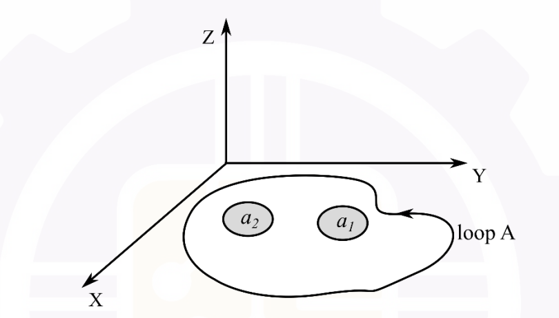
What is the expression for the induced rms voltage in loop A?
Which law is synonymous to the occurrence of diamagnetism?
Two resistors are connected in a circuit loop of area $5 \ m^2$, as shown in the figure below. The circuit loop is placed on the x-y plane.
When a time-varying magnetic flux, with flux-density $B(t) = 0.5t$ (in Tesla), is applied along the positive z-axis, the magnitude of current $I$ (in Amperes, rounded off to two decimal places) in the loop is __________.
If a copper conductor is moved across a magnetic field -
- Faraday's law of electromagnetic induction is mathematically described by which one of the following equations?