A metallic strain-gauge (SG) with resistance $R_{SG}$ is connected as shown in the figure, where $R_{L1}$, $R_{L2}$, $R_{L3}$ represent the lead wire resistances. The SG has a gauge factor of 2 and nominal resistance $R_N$ of 125 $\Omega$. When the SG is subjected to a tensile strain of $2 \times 10^{-3}$, the resulting change in $R_{SG}$ is $\Delta R$. The $\Delta R$ value is measured as $\Delta R_{MEAS} = R_{EQ2} - R_{EQ1}$. The $R_{EQ1}$ and $R_{EQ2}$ are the equivalent resistances measured between the terminals 1 and 2, and terminals 2 and 3, respectively.
If $R_{L1} = R_{L2} = 5 \ \Omega$, and $R_{L3} = 4.95 \ \Omega$, the measured value of tensile strain is ______ $\times 10^{-3}$ (rounded off to two decimal places).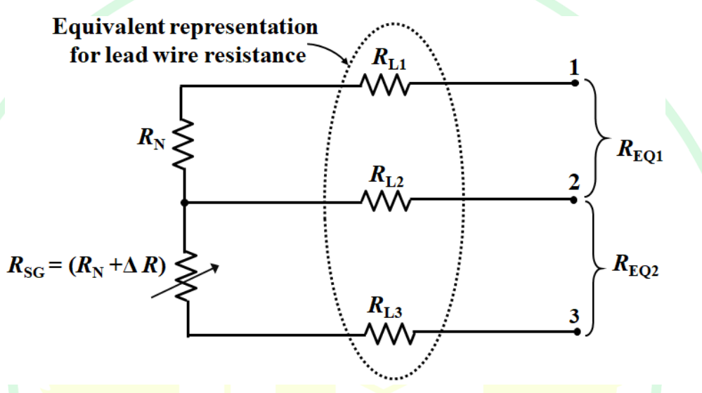
The problem involves calculating the measured tensile strain using a strain-gauge circuit. The given parameters are:
- Gauge factor, \( GF = 2 \)
- Nominal resistance, \( R_N = 125 \, \Omega \)
- Strain, \( \varepsilon = 2 \times 10^{-3} \)
- Lead resistances: \( R_{L1} = R_{L2} = 5 \, \Omega \), \( R_{L3} = 4.95 \, \Omega \)
The change in strain-gauge resistance is given by:
\[\Delta R = GF \times R_N \times \varepsilon\]
Substituting the values:
\[\Delta R = 2 \times 125 \times 2 \times 10^{-3} = 0.5 \, \Omega\]
The measured resistances are:
\( R_{EQ1} = R_N + R_{L1} + R_{L2} = 125 + 5 + 5 = 135 \, \Omega \)
\( R_{EQ2} = R_{SG} + R_{L2} + R_{L3} = (R_N + \Delta R) + 5 + 4.95 \)
\( R_{EQ2} = (125 + 0.5) + 5 + 4.95 = 135.45 \, \Omega \)
The measured change in resistance:
\(\Delta R_{MEAS} = R_{EQ2} - R_{EQ1} = 135.45 - 135 = 0.45 \, \Omega\)
The measured tensile strain, \( \varepsilon_{MEAS} \), is calculated using:
\(\varepsilon_{MEAS} = \frac{\Delta R_{MEAS}}{GF \times R_N}\)
Substitute the values:
\(\varepsilon_{MEAS} = \frac{0.45}{2 \times 125} = 0.0018 = 1.8 \times 10^{-3}\)
The calculated strain is 1.8 which falls within the given range of 1.75 to 1.85.
Important Questions from Resistive Transducers
Flow can be measured by ____.
- Active strain gauges are connected in a half-bridge configuration to measure strain in a cantilever element. When powered by a voltage source of 10 V, the voltage at the output of the bridge is 1 mV. If the gauge factor is 2.5, the strain in the cantilever element is ________ microstrain.
An engineer is designing a feedback control system using a potentiometer transducer to measure angular position. What is the primary effect if a voltmeter with low resistance is connected to measure the potentiometer output?
- A wire-wound ‘resistive potentiometer type' angle sensor with 72 turns is used in an application. The first turn of the potentiometer is connected to ground while its last turn is connected to 3.6 V. The width of the wiper covers two turns ensuring make-before-break. The output (wiper) voltage when the wiper is on top of both the turns 35 and 36 is ________ V (rounded off to two decimal places).
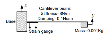
A strain gauge is attached on a cantilever beam as shown. If the base of the cantilever vibrates according to the equation \[ x(t) = \sin \omega_1 t + \sin \omega_2 t, \] where \(2~\text{rad/s} < \omega_1, \omega_2 < 3~\text{rad/s}\), then the output of the strain gauge is proportional to