Potentiometer Voltage Calculation
This solution explains the calculation of output voltage for a wire-wound angle sensor potentiometer.
Potentiometer Parameters
- Total Turns: 72
- Voltage Range: 0 V (Ground) to 3.6 V
- Total Voltage Swing: $3.6 \text{ V}$
- Wiper Position: On turns 35 and 36
Voltage Resolution Calculation
The voltage is distributed uniformly across all turns. The voltage change per turn ($V_{per\_turn}$) is:
$V_{per\_turn} = \frac{3.6 \text{ V}}{72 \text{ turns}} = 0.05 \text{ V/turn}$
Wiper Position Determination
The wiper spans turns 35 and 36. The effective position is the average turn number:
$Effective\_turn = \frac{35 + 36}{2} = 35.5$
Final Output Voltage
Calculate the output voltage ($V_{out}$) using the effective turn position:
$V_{out} = Effective\_turn \times V_{per\_turn}$
$V_{out} = 35.5 \times 0.05 \text{ V} = 1.775 \text{ V}$
Rounded to two decimal places, the output voltage is 1.78 V.
Important Questions from Resistive Transducers
Flow can be measured by ____.
- Active strain gauges are connected in a half-bridge configuration to measure strain in a cantilever element. When powered by a voltage source of 10 V, the voltage at the output of the bridge is 1 mV. If the gauge factor is 2.5, the strain in the cantilever element is ________ microstrain.
An engineer is designing a feedback control system using a potentiometer transducer to measure angular position. What is the primary effect if a voltmeter with low resistance is connected to measure the potentiometer output?
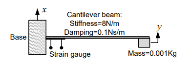
A strain gauge is attached on a cantilever beam as shown. If the base of the cantilever vibrates according to the equation \[ x(t) = \sin \omega_1 t + \sin \omega_2 t, \] where \(2~\text{rad/s} < \omega_1, \omega_2 < 3~\text{rad/s}\), then the output of the strain gauge is proportional to
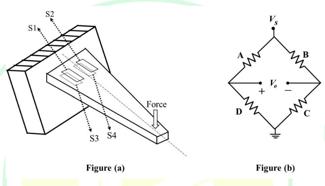
In the force transducer shown in Figure (a), four identical strain gauges S1, S2, S3, and S4 are mounted on a cantilever at equal distance from its base. S1 and S2 are mounted on the top surface and S3 and S4 are mounted on the bottom surface, as shown in the Figure (a). These strain gauges are to be connected to form a Wheatstone bridge consisting of four arms A, B, C, and D, as shown in the Figure (b). From the following options, the correct order to maximize the measurement sensitivity is