
(d)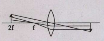
Understanding Ray Diagrams for Convex Lenses
This question asks us to identify the correct ray diagram for image formation using a thin convex lens. A convex lens is a converging lens that refracts parallel light rays towards a focal point. The way light rays behave depends on where the object is placed relative to the lens's principal focus (\(F_1\)) and optical center (O). We need to check which diagram correctly follows the established rules of ray tracing.
Rules of Ray Tracing for Convex Lenses
To draw a ray diagram for a convex lens, we typically use three principal rays originating from the top of the object:
- Ray 1: A ray parallel to the principal axis. After passing through the lens, it refracts and passes through the principal focus on the opposite side (let's call it \(F_2\)).
- Ray 2: A ray passing through the optical center (O) of the lens. This ray goes undeviated.
- Ray 3: A ray passing through the principal focus on the same side as the object (let's call it \(F_1\)). After passing through the lens, this ray becomes parallel to the principal axis.
The point where these refracted rays intersect (or their virtual extensions intersect) is where the image is formed. For a convex lens, if the object is placed beyond the principal focus (\(F_1\)), a real and inverted image is formed on the opposite side.
Analyzing the Ray Diagram Options
Let's analyze each figure based on the rules and common scenarios of image formation by a convex lens:
Option (a) Analysis
In this diagram, the object is placed between \(F_1\) and \(2F_1\). The diagram shows the parallel ray refracting through \(F_2\) and the central ray going straight. These rays appear to intersect beyond \(2F_2\), forming a real, inverted, and magnified image. This scenario is consistent with the rules.
Option (b) Analysis
Here, the object is placed beyond \(2F_1\). According to the rules, the image should be formed between \(F_2\) and \(2F_2\), and it should be real, inverted, and diminished. However, the diagram shows the image being formed beyond \(2F_2\). Thus, this diagram is incorrect.
Option (c) Analysis
In this case, the object is placed at the principal focus \(F_1\). The refracted rays (parallel ray through \(F_2\) and the central ray straight) should emerge parallel to each other, forming the image at infinity. The diagram incorrectly shows the rays converging to form a real image at a finite distance. Thus, this diagram is incorrect.
Option (d) Analysis
This diagram shows the object placed between \(F_1\) and \(2F_1\). The ray parallel to the principal axis is shown refracting through \(F_2\). The ray passing through the optical center O is shown going undeviated. The intersection of these two rays occurs beyond \(2F_2\), forming an image that is real, inverted, and magnified. This accurately represents the situation.
Verifying with the Lens Formula
We can use the lens formula to confirm the image position. The formula is:
\(\frac{1}{v} - \frac{1}{u} = \frac{1}{f}\)Where f is the focal length (positive for convex lens), u is the object distance (negative when the object is on the left), and v is the image distance (positive for real images on the right).
Let's assume the distances marked on the axis are proportional. If we set the distance \(OF_1 = F_1(2F_1) = F_2(2F_2) = f\).
In diagram (d), the object appears to be placed at u = -1.5f (midway between \(F_1\) and \(2F_1\)). Plugging this into the lens formula:
\(\frac{1}{v} - \frac{1}{-1.5f} = \frac{1}{f}\) \(\frac{1}{v} + \frac{1}{1.5f} = \frac{1}{f}\) \(\frac{1}{v} = \frac{1}{f} - \frac{1}{1.5f} = \frac{1}{f} - \frac{2}{3f} = \frac{3-2}{3f} = \frac{1}{3f}\) v = 3fThis calculation shows that if the object is placed at 1.5f from the lens, the image is formed at 3f. Diagram (d) visually aligns well with this result, showing the image formed significantly beyond \(2F_2\). Diagram (a) also shows a similar scenario, but the proportions in (d) are more accurate based on this calculation.
Conclusion
Based on the rules of ray tracing and verification using the lens formula, diagram (d) correctly illustrates the formation of a real, inverted, and magnified image when the object is placed between the principal focus (\(F_1\)) and twice the focal length (\(2F_1\)) of a thin convex lens.
Similar Questions
- In a Telescope, compared to the eyepiece lens the objective lens has
An object is placed between infinity and the pole (P) of a convex mirror. The position of the image is
When a light ray passes through from air to water with a non-zero angle the ray will be
If the speed of light in carbon disulfide and vacuum is X and Y respectively, then
Important Questions from Optics
Which among the following is used as a reflector in search lights?
The incident ray, the ray perpendicular to the point of incidence, and the reflected ray all lie________.
Which is the only event to prove that light is a transverse wave?
A. Scattering of light
B. Interference
C. Diffraction
D. Polarisation
In which a convex mirror is used?
A. Rear View mirrors in vehicles
B. Glass windows
C. Makeup Mirror
D. Kaleidoscope
Which mirror is preferred as a rear-view (wing) mirror in vehicles because of its wider field of view?



